- A special kind of class diagram that focuses on a system’s nodes.
- Show the structure of the run-time system.
- It one of the two kinds of UML diagrams used for the physical aspects of an OO system.
Graphically, a deployment diagram is a collection of vertices and arcs. Deployment diagrams commonly contain Nodes and Dependency & association relationships. It may also contain notes and constraints.
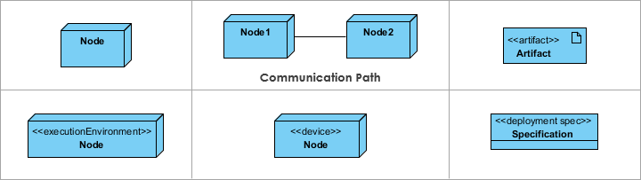
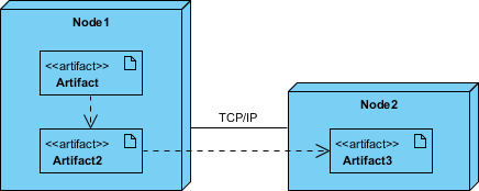
- 3-D box represents a node, either software or hardware
- Hardware node can be signified with <<stereotype>> i.e. <<artifact>> or <<mainframe>>
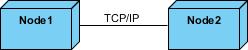
- Connections between nodes are represented with a line, with optional <<stereotype>>
- Nodes can reside within a node
Deployment Planning
- Design and plan how will your system be installed?
- Determine if different versions of the system will be deployed at the same time, how will you resolve differences?
- What physical sites do you need to deploy to and in what order?
- How will you train your users?
- What backups do you need before installation?
- Do you need to do a data conversion?
How to Develop a Deployment diagram?
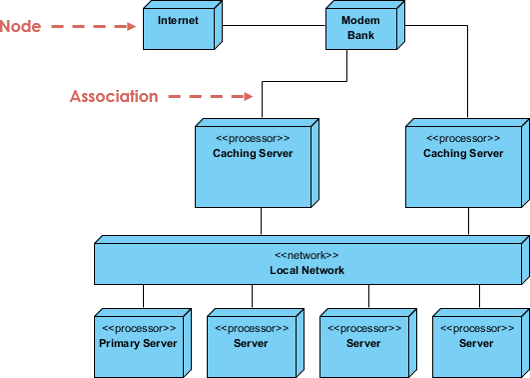
Firstly, identify the nodes that represent your system’s client and server processors and then highlight those devices that are relevant to the behavior of your system.
For example, you’ll want to model special devices, such as credit card readers, badge readers, and display devices other than monitors, because their placement in the system’s hardware topology are likely to be architecturally significant. · Provide visual cues for these processors and devices via stereotyping. · Model the topology of these nodes in a deployment diagram. Similarly, specify the relationship between the components in your system’s implementation view and the nodes in your system’s deployment view.
Nodes
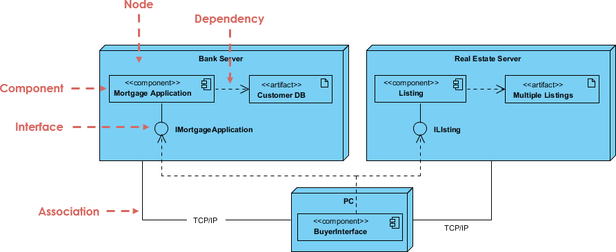
A node usually represents a piece of hardware in the system. A connection depicts the communication path used by the hardware to communicate usually indicates the method i.e. TCP/IP
Artifacts
- An artifact is the specification of a physical piece of information, such as, source files, binary executable files, table in a database system.
- An artifact is defined by the user represents a concrete element in the physical world.
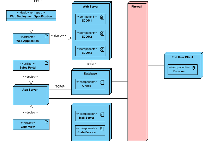
Deployment Diagram Example
Summary
A deployment diagram helps to model the physical aspects of an object-oriented software system. It visualizes the runtime configuration in a static view and visualizes the distribution of components in the application. In most cases, it involves modeling the hardware configuration and software components.
Reference
