


UML Package Diagram is a type of Unified Modeling Language (UML) diagram that (such as classes, interfaces, and other packages) into packages. These diagrams help by providing a .
Key Concepts of UML Package Diagrams
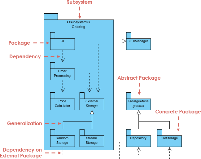
1. Packages
- Definition: A package is a namespace that groups related elements (e.g., classes, interfaces, other packages).
- Purpose: To organize and modularize the system, making it easier to manage and understand.
- Example: A package named
com.example.ecommercemight contain classes related to an e-commerce system.
2. Package Dependencies
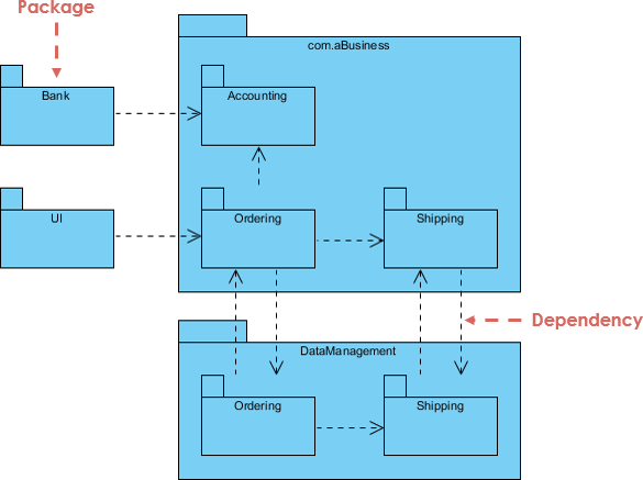
- Definition: Dependencies between packages indicate that one package uses or depends on another.
- Purpose: To show how packages interact and rely on each other.
- Example: The
com.example.ecommerce.orderpackage might depend on thecom.example.ecommerce.userpackage.
3. Package Elements
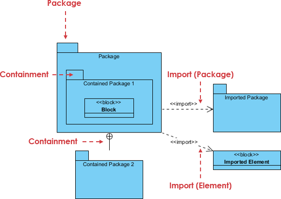
- Classes and Interfaces: Packages can contain classes and interfaces, which are the building blocks of the system.
- Sub-Packages: Packages can contain other packages, creating a .
- Example: The
com.example.ecommercepackage might contain sub-packages likeuser,order, andpayment.
4. Visibility and Accessibility
- Public and Private Elements: Packages can define the visibility of their elements (e.g., public, private, protected).
- Purpose: To within the system.
- Example: A class marked as
publiccan be accessed by other packages, while aprivateclass is only accessible within its own package.
5. Benefits of UML Package Diagrams
- Modularity: Helps in organizing large systems into smaller, manageable units.
- Clarity: Provides a clear view of the system’s structure and dependencies.
- Collaboration: Facilitates communication between developers and stakeholders.
- Documentation: Serves as a .
6. Example Use Case
:
-
Packages:
com.example.ecommerce.user: Contains classes related to user management.com.example.ecommerce.order: Contains classes related to order management.com.example.ecommerce.payment: Contains classes related to payment processing.
-
Dependencies:
com.example.ecommerce.orderdepends oncom.example.ecommerce.user.com.example.ecommerce.paymentdepends oncom.example.ecommerce.order.
-
Classes:
Userclass incom.example.ecommerce.user.Orderclass incom.example.ecommerce.order.Paymentclass incom.example.ecommerce.payment.
- UML Package Diagrams organize and group related elements into packages, providing a high-level view of the system’s structure.
- They help manage complexity, clarify dependencies, and facilitate collaboration.
- Packages can contain classes, interfaces, and other packages, creating a hierarchical structure.
- Visibility and accessibility controls ensure proper encapsulation and access within the system.
This tutorial outlines the steps for generating and refining UML Package Diagrams instantly using the Visual Paradigm Chatbot feature, as demonstrated in the product demo.
Generating and Refining UML Package Diagrams using the Visual Paradigm Chatbot
Step 1: Accessing the Chatbot and Initial Generation
To begin generating a UML package diagram using the visual paradigm chatbot, navigate to tools chatbot. Once the chatbot is open, you can request the generation of a package diagram, such as generating one for the onboard flight management system.
Step 2: Refining the Diagram
If the initial generated diagram seems too generic, you can ask the chatbot to revise it. For instance, you might ask the chatbot to revise the diagram to be more focused on flight control.
Step 3: Correcting Missing Relationships
The generated diagram may sometimes miss certain elements, such as failing to generate relationships to a specific package (e.g., the aileron’s package). If this occurs, you can ask the chatbot to fix it.
Step 4: Updating Incorrect Linkages
After requesting a fix, the chatbot might add the required relationships but link them to the wrong target. You can ask the chatbot to update this to correct the linkages.
Step 5: Adding Specific Details
To further customize the diagram, you can ask the chatbot to add new elements. For example, you can ask the chatbot to add speed brake and flaps to the actuators package.
Step 6: Comparing Versions (Optional Review)
While iterating and refining the diagram, you can use the compare with previous button. This feature allows you to compare the current diagram with the previous version you generated.
Step 7: Importing and Finalizing the Diagram
To save the diagram and make it a permanent part of your work, you need to persist this diagram by import it into your current visual paradigm project. To perform the import, press the import to visual paradigm button. Once the import is finished, the diagram is converted into the visual paradigm desktop format and is ready for further editing.
Visual Paradigm Package Diagram Resources
Here is a comprehensive list of official resources, guides, tutorials, and tools from Visual Paradigm for Package Diagrams (a UML structural diagram used to organize model elements, show dependencies, and structure large-scale projects):
- What is Package Diagram?https://www.visual-paradigm.com/guide/uml-unified-modeling-language/what-is-package-diagram/ (Introductory guide with explanations, examples, and how packages group UML elements.)
- How to Draw Package Diagram?https://www.visual-paradigm.com/support/documents/vpuserguide/94/2583/7192_drawingpacka.html (Step-by-step tutorial on creating package diagrams in Visual Paradigm.)
- Package Diagram in Visual Paradigmhttps://www.visual-paradigm.com/support/documents/vpuserguide/94/2583_packagediagr.html (Detailed chapter on creating and using package diagrams.)
- Package Diagram Tutorial (Online Version)https://online.visual-paradigm.com/diagrams/tutorials/package-diagram-tutorial/ (Interactive tutorial with examples, tips, and free online drawing tool.)
- What is Package Diagram? How to Draw Package Diagram?https://www.visual-paradigm.com/tutorials/packagediagram.jsp (In-depth tutorial with project organization examples and navigation features.)
- UML Package Diagram: Unveiling the Architecturehttps://guides.visual-paradigm.com/uml-package-diagram-unveiling-the-architecture/ (Guide focusing on architecture visualization, dependencies, and nesting.)
- Online Package Diagram Software/Toolhttps://online.visual-paradigm.com/diagrams/features/package-diagram-software/ (Free online editor for creating package diagrams with examples.)
- Package Diagram Templateshttps://online.visual-paradigm.com/diagrams/templates/package-diagram/ (Ready-to-use professional templates for package diagrams.)
- Package Diagram Gallery/Examplehttps://www.visual-paradigm.com/VPGallery/diagrams/Package.html (Visual examples of package diagrams.)
- Beginner’s Guide to Package Diagrams with Visual Paradigm Onlinehttps://blog.visual-paradigm.com/beginners-guide-to-package-diagrams-with-visual-paradigm-online/ (Blog tutorial for beginners using the online tool.)
Visual Paradigm AI UML Diagram Generation Resources
Visual Paradigm offers powerful AI features for generating UML diagrams (including package diagrams where applicable) from text prompts, descriptions, or ideas. These include text-to-diagram tools, chatbots, and generators:
- AI Diagram Generation Guidehttps://guides.visual-paradigm.com/visual-paradigm-ai-diagram-generation-guide/ (Step-by-step guide to instantly creating UML and other diagrams with AI from text.)
- AI Chatbot for Diagramming & Modelinghttps://chat.visual-paradigm.com/ (Main AI chatbot tool: Generate UML diagrams via text prompts, refine, and export.)
- Visual Paradigm AI Chatbot Featureshttps://www.visual-paradigm.com/features/ai-chatbot/ (Overview of generating UML, SysML, etc., with conversational AI.)
- Instantly Generate Complex Diagrams with AI Diagram Generatorhttps://updates.visual-paradigm.com/releases/ai-diagram-generator/ (Announcement and guide for generating UML types like Class, Sequence, Use Case from prompts.)
- AI-Assisted UML Class Diagram Generator (extendable to other UML) https://www.visual-paradigm.com/features/ai-assisted-uml-class-diagram-generator/https://ai.visual-paradigm.com/tool/ai-assisted-uml-class-diagram-generator/ (Guided AI tool for UML class diagrams with generation and analysis.)
- Generate UML Sequence Diagrams Instantly with AIhttps://blog.visual-paradigm.com/generate-uml-sequence-diagrams-instantly-with-ai/ (Demo and blog on AI generation for sequence diagrams; similar for other UML.)
These resources are primarily from the official Visual Paradigm website (as of December 2025). For hands-on use, many link to free online tools or trials. If you’re working with TOGAF or enterprise architecture, package diagrams can be organized within models, and AI tools accelerate UML creation across phases.
