


1. Introduction to the C4 Model
The C4 model is a for visualizing and documenting software architecture. It provides a structured way to describe a software system at different levels of abstraction, making it accessible to both technical and non-technical stakeholders.
Why Use the C4 Model?
- Clarity: It breaks down complex systems into manageable levels.
- Consistency: It enforces a standardized approach to documentation.
- Flexibility: It can be used for small applications or large-scale enterprise systems.
- Collaboration: It facilitates communication between developers, architects, and business stakeholders.
2. The Four Core Levels of the C4 Model
Level 1: System Context Diagram
Purpose: Shows how the software system fits into its environment. Key Concepts:
- People (Actors): Users or external systems interacting with the system.
- Systems: External software systems (e.g., databases, APIs, third-party services).
Example: For an Internet Banking System, the context diagram would show:
- Personal Customers (people)
- Mainframe Banking System (external system)
- E-mail System (external system)
Audience: Technical and non-technical stakeholders.
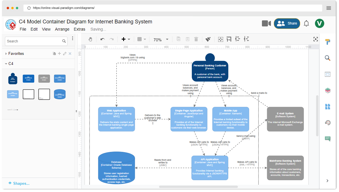
Level 2: Container Diagram
Purpose: Opens the “black box” of the system to reveal its high-level technical building blocks. Key Concepts:
- Containers: Independently deployable units (e.g., web apps, microservices, databases).
- Technology Choices: Programming languages, frameworks, and data storage solutions.
Example: For the Internet Banking System, the container diagram might include:
- Single-Page Application (Angular)
- Web Application (Java/Spring MVC)
- API Application (Java/Spring MVC)
- Database (MySQL)
Audience: Architects and developers.
Level 3: Component Diagram
Purpose: Zooms into a single container to show its internal structure. Key Concepts:
- Components: Logical groupings of related code/functionality.
- Responsibilities: What each component does.
- Interactions: How components communicate.
Example: For the API Application container, the component diagram might show:
- Spring MVC Rest Controllers
- Repository Components (for database access)
- Mainframe Banking System Facade
Audience: Technical team members.
Level 4: Code-Level Diagrams
Purpose: Illustrates low-level implementation details. Key Concepts:
- UML Class Diagrams: Show classes, interfaces, and relationships.
- Optional: Often derived directly from the source code.
Example: A UML class diagram for the Mainframe Banking System Facade component.
Audience: Software developers.
3. Key Concepts of the C4 Model
- The C4 model allows users to zoom in and out, from the big picture (System Context) to granular details (Code).
- Each level builds on the previous one, ensuring consistency.
- A container is any separately runnable or deployable unit (e.g., a microservice, a database).
- Communication between containers often involves network calls.
Consistency and Scoping
- A Component Diagram is always scoped within a specific Container.
- Components reside inside containers and are not independently deployable.
Optional Detail (Level 4)
- Code-level diagrams are optional because developers can often derive this information from the source code.
4. Visual Paradigm’s C4 Ecosystem

Comprehensive C4 Model Scope
- Supports all six C4 diagram types (Context, Container, Component, System Landscape, Dynamic, Deployment).
- Enforces hierarchical clarity and consistency.
Extensive Visual Modeling Features
- : Assists in drafting initial content for diagrams.
- Multi-Platform Modeling: Supports UML, SysML, ERD, BPMN, and ArchiMate.
- Professional Toolkit: Includes custom attributes, lifecycle management, and smart features.
AI-Driven Compliance and Workflow
- Standards Enforcement: Automatically applies C4 notation and best practices.
- : Translates natural language into PlantUML code.
- : Allows users to refine diagrams via text prompts.
5. Practical Examples
Example 1: Internet Banking System
- System Context Diagram: Shows the banking system, personal customers, and external systems.
- Container Diagram: Reveals the web app, API, and database.
- Component Diagram: Details the API’s internal structure.
- Code-Level Diagram: UML class diagram for the Mainframe Banking System Facade.
Example 2: E-Commerce Platform
- System Context Diagram: Shows the e-commerce system, customers, payment gateways, and shipping services.
- Container Diagram: Includes the frontend (React), backend (Node.js), and database (MongoDB).
- Component Diagram: Details the backend’s microservices (e.g., Order Service, Payment Service).
- Code-Level Diagram: UML class diagram for the Order Service.
6. Best Practices for Using the C4 Model
- Start with the System Context: Begin with the big picture before diving into details.
- Keep Diagrams Simple: Avoid clutter; focus on clarity.
- Use Consistent Notation: Stick to C4 standards for diagrams.
- Leverage AI Tools: Use tools like Visual Paradigm for automation and compliance.
- Iterate and Refine: Update diagrams as the system evolves.
7. Conclusion
The C4 model is a powerful framework for documenting software architecture. By breaking down systems into hierarchical levels, it ensures clarity, consistency, and collaboration. Tools like Visual Paradigm enhance the process with AI-driven features, making it easier to create and maintain C4 diagrams.
Next Steps:
- Start with a System Context Diagram for your project.
- Use Visual Paradigm or similar tools to automate and refine your diagrams.
- Iterate as your system evolves.
- C4-PlantUML Studio | AI-Powered C4 Diagram Generator (matches “AI-Powered C4 PlantUML Studio (C4-PlantUML Studio)” and “AI-Powered C4 Diagram Generator”)
- AI-Powered C4 Diagram Generator | Create Architecture Diagrams from Text (related AI tool entry point)
- C4 Component Diagram: A Definitive Guide to Your Code’s Internal Structure with AI (linked in multiple guide pages, e.g., from C4 System Context Guide)
- C4 Container Diagram: A Definitive Guide to Visualizing Your Software’s Building Blocks with AI (linked in multiple guide pages, e.g., from C4 System Context Guide)
- C4 Deployment Diagram (direct AI tool page for generating C4 Deployment Diagrams)
- C4 System Context Diagram: A Definitive Guide to Seeing the Big Picture with AI
- Generate the Complete C4 Model Instantly with Visual Paradigm’s AI Diagram Generator (featured in product updates, e.g., Visual Paradigm Desktop Updates)
- Streamline C4 Diagrams with Our New AI-Powered Markdown Editor (no exact matching page found; may be an older or internal feature reference)
- The Ultimate AI C4 Diagram Tool & Modeling Software
- New: Full C4 Model Support Added to Visual Paradigm Desktop (announced in AI Diagram Generator Release)
- C4 Diagram Tool & Modeling Software (core landing page for C4 tools)
