


“The state of an object is not just where it is—it’s what it can do, what it’s waiting for, and how it reacts to the world.”
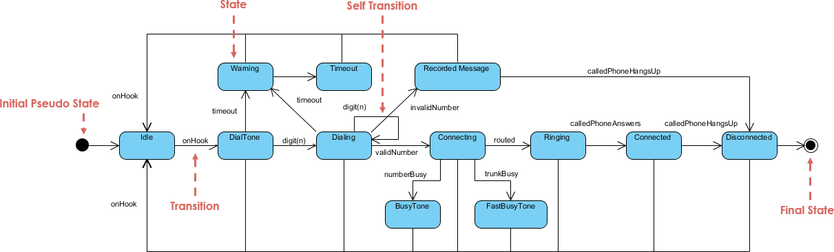
In modern software design, understanding behavior over time is as critical as defining structure or interaction. While Class Diagrams show what an object is, and Sequence Diagrams show how it interacts, UML State Machine Diagrams (also known as State Diagrams) reveal the inner life of an object — its lifecycle, reactive behavior, and conditional responses.
This comprehensive guide walks you through the core principles, advanced techniques, best practices, integration with other UML diagrams, and a practical workflow for creating robust, maintainable state diagrams. We’ll also explore how Visual Paradigm’s AI Visual Modeling Platform can accelerate your modeling process — and conclude with error-free PlantUML code for real-world examples.
1. Why State Diagrams Are Uniquely Powerful
State Machine Diagrams focus on behavior over time — particularly the dynamic lifecycle of a single object or component. Unlike:
| Diagram Type | Focus | Limitation |
|---|---|---|
| Class Diagram | Static structure (classes, attributes, relationships) | Doesn’t show behavior evolution |
| Sequence Diagram | Interaction flow between objects | Lacks persistent state tracking |
| Activity Diagram | Procedural flow (actions, decisions, concurrency) | Less emphasis on object state |
✅ State Diagrams excel at modeling:
Objects with lifecycle phases (e.g., Order, User Session)
Event-driven systems (e.g., UIs, embedded devices, protocols)
Conditional behavior where the same event triggers different outcomes based on current state
They are especially powerful for reactive systems, where the object’s response depends on its current state — making them indispensable in domains like e-commerce, IoT, embedded systems, and network protocols.
2. Top Use Cases for State Diagrams
✅ E-commerce Order Lifecycle
An order doesn’t just exist — it evolves:
-
Placed → Paid → Shipped → Delivered → (Returned or Cancelled)
Events:pay(),ship(),deliver(),cancel()
✅ UI/UX State Management
A login form behaves differently depending on input:
-
Empty → Validating → Valid → Invalid → Submitting → Success/Error
💡 The submit button is disabled when the form is invalid — this is state-dependent behavior.
✅ Embedded Systems & IoT Devices
A smart thermostat or sensor:
-
Idle → Sensing → Processing → Transmitting → LowPower (Sleep)
Triggers: timer expiry, threshold breach, battery level
✅ Network Protocols (Classic Example: TCP)
The TCP connection lifecycle is a textbook case:
-
CLOSED → LISTEN → SYN_SENT → SYN_RECEIVED → ESTABLISHED → FIN_WAIT_1 → TIME_WAIT → CLOSED
Each state represents a protocol phase; transitions are driven by packets received (SYN, ACK, FIN) or application calls.
3. Essential Skills & Advanced Techniques
Go beyond basic states and arrows. Master these to model real-world complexity.
🔹 Guard Conditions
Transitions only occur if a condition is met.
Example:
pay() [total > 0 && paymentMethodValid] / updateInventory()
⚠️ Prevent invalid transitions (e.g., paying with a zero amount).
🔹 Entry, Exit, and Do Actions
These define behavior tied to state lifecycle, not just transitions.
| Action Type | When It Executes | Example |
|---|---|---|
entry / startTimer() |
On entering the state | Start monitoring |
exit / logStateChange() |
On leaving the state | Log transition |
do / monitorTemperature() |
Continuously while in state | Ongoing activity |
📌 These follow Moore Machine semantics: actions are associated with states, not transitions.
🔹 Composite States (Hierarchical States)
Break down complex states into substates for clarity and reuse.
Example: Order “Fulfilling” Composite State
Fulfilling
├── VerifyingPayment
├── Packaging
└── QualityCheck
-
Entering
Fulfillingdefaults toVerifyingPayment. -
Exiting
Fulfillingexits all substates. -
Substates can have their own transitions and actions.
✅ Reduces clutter and enables reuse across models.
🔹 Orthogonal Regions (Parallel States)
Model concurrent, independent behaviors within a single object.
Example: Car Infotainment System in “Active” state
Active
├── Radio: On ↔ Paused
└── Navigation: Idle → Routing → Rerouting
-
Both regions run in parallel.
-
Events in one region don’t affect the other (e.g., changing radio doesn’t stop navigation).
✅ Ideal for systems with independent subsystems (e.g., UI + backend, device + network).
4. Integrating State Diagrams with Other UML Diagrams
State Diagrams are not standalone — they thrive in context.
| UML Diagram | How It Connects to State Diagram |
|---|---|
| Use Case Diagram | Use Cases (e.g., “Place Order”) define the purpose; State Diagrams show how the object evolves to fulfill it. |
| Class Diagram | Class attributes (e.g., status: OrderStatus, isPaid: boolean) support state logic. |
| Sequence Diagram | Messages (e.g., order.pay()) become events triggering transitions. |
| Activity Diagram | Activity shows “how” (flow), State Diagram shows “what state” the object is in during that flow. |
🔄 Best Practice: Use Sequence Diagrams to identify triggers, then map them to State Diagram transitions.
5. Practical Workflow: The State Diagram Pipeline
Follow this proven, iterative workflow:
Step 1: Identify the “Heavy Lifters”
Only model state-rich objects:
-
Lifecycle-managed entities (Order, User Session, Payment)
-
Mode-dependent systems (Thermostat, Device Mode)
-
Protocol implementations (TCP, MQTT)
❌ Avoid modeling simple data holders (e.g.,
Address).
Step 2: Define the Steady States
Brainstorm stable conditions the object can be in:
-
Placed, Paid, Shipped, Delivered, Cancelled
-
Idle, Active, Sleeping
-
Closed, Listening, Established
✅ Use nouns or adjectives — not verbs.
Step 3: Map Events & Triggers
Review Sequence Diagrams or Use Cases to identify:
-
Method calls (
order.cancel(),device.turnOn()) -
External signals (timer, sensor data, user input)
These become events on transitions.
Step 4: Add Guards and Actions
Refine with:
-
Guards to prevent invalid transitions
-
Entry/Exit/Do actions for side effects
✅ Example:
exit / notifyAdmin()when order is cancelled.
Step 5: Validate & Iterate
Cross-check with:
-
Class Diagram: Ensure required attributes exist
-
Sequence Diagram: Verify all triggers are covered
-
Simulation: Walk through real scenarios (e.g., “Can a delivered order be cancelled?”)
✅ Use test cases to validate completeness.
6. Pro-Tip: The “Wait” State Principle
❗ A state should represent a stable condition where the object is waiting for an event.
✅ Good States (Wait States):
-
WaitingForPayment -
AwaitingShipment -
Idle -
Listening
❌ Bad States (Not Wait States):
-
CalculateTotal— this is an instantaneous action, not a state. -
SendEmail— a transition action, not a state.
✅ Fix: Move such logic to transition actions or do activities in a waiting state.
7. Real-World Examples in PlantUML
Below are error-free, fully functional PlantUML code for three classic scenarios. Copy and paste into PlantUML Online or Visual Paradigm to render.
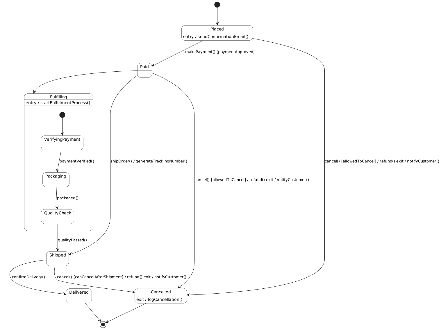
🟩 Example 1: E-commerce Order Lifecycle (Composite + Guards)
@startuml
skinparam shadowing false
skinparam state {
    BackgroundColor #FFFFFF
    BorderColor #000000
    FontSize 14
}

[*] --> Placed
Placed --> Paid : makePayment() [paymentApproved]
Paid --> Shipped : shipOrder() / generateTrackingNumber()
Shipped --> Delivered : confirmDelivery()

' Composite State: Fulfilling
state Fulfilling {
    [*] --> VerifyingPayment
    VerifyingPayment --> Packaging : paymentVerified()
    Packaging --> QualityCheck : packaged()
    QualityCheck --> Shipped : qualityPassed()
}

Paid --> Fulfilling

' Cancel transition with guard
Placed --> Cancelled : cancel() [allowedToCancel] / refund() exit / notifyCustomer()
Paid --> Cancelled : cancel() [allowedToCancel] / refund() exit / notifyCustomer()
Shipped --> Cancelled : cancel() [canCancelAfterShipment] / refund() exit / notifyCustomer()

' Final state
Delivered --> [*]
Cancelled --> [*]

' Entry actions
Placed : entry / sendConfirmationEmail()
Fulfilling : entry / startFulfillmentProcess()
Cancelled : exit / logCancellation()
@enduml
✅ Features: Composite state, guards, entry/exit actions, clean flow.
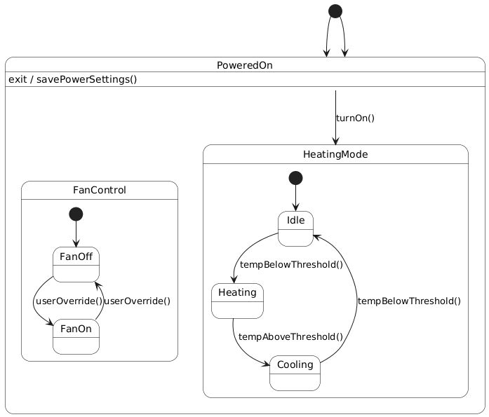
🟩 Example 2: Smart Home Thermostat (Orthogonal Regions)
@startuml
skinparam shadowing false
skinparam state {
    BackgroundColor #FFFFFF
    BorderColor #000000
    FontSize 14
}

[*] --> PoweredOn

state PoweredOn {
    ' Orthogonal Region 1: Heating/Cooling Mode
    state HeatingMode {
        [*] --> Idle
        Idle --> Heating : tempBelowThreshold()
        Heating --> Cooling : tempAboveThreshold()
        Cooling --> Idle : tempBelowThreshold()
    }

    ' Orthogonal Region 2: Fan Control
    state FanControl {
        [*] --> FanOff
        FanOff --> FanOn : userOverride()
        FanOn --> FanOff : userOverride()
    }
}

' Transition from PoweredOn to HeatingMode
PoweredOn --> HeatingMode : turnOn()

' Exit actions
PoweredOn : exit / savePowerSettings()

' Final state
[*] --> PoweredOn

@enduml
✅ Features: Orthogonal regions, concurrent behavior, clear separation of concerns.
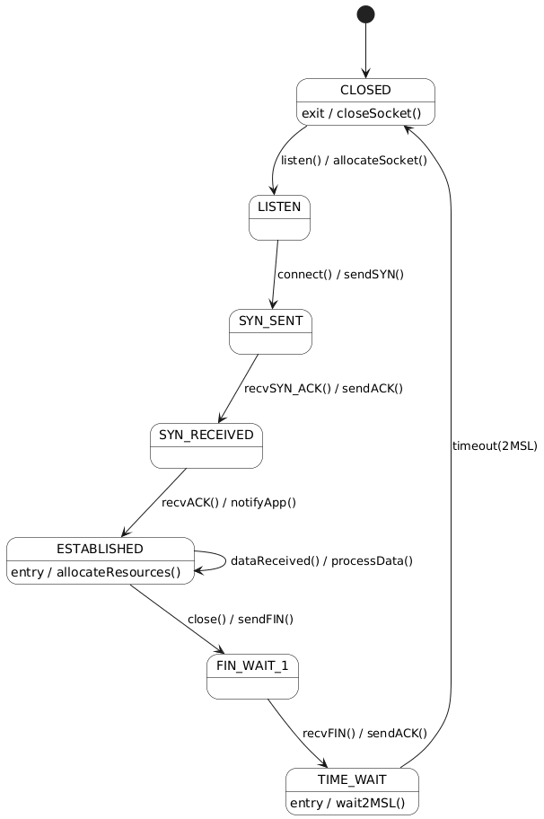
🟩 Example 3: TCP Connection Lifecycle (Classic Protocol)
@startuml
skinparam shadowing false
skinparam state {
    BackgroundColor #FFFFFF
    BorderColor #000000
    FontSize 14
}

[*] --> CLOSED
CLOSED --> LISTEN : listen() / allocateSocket()
LISTEN --> SYN_SENT : connect() / sendSYN()
SYN_SENT --> SYN_RECEIVED : recvSYN_ACK() / sendACK()
SYN_RECEIVED --> ESTABLISHED : recvACK() / notifyApp()
ESTABLISHED --> FIN_WAIT_1 : close() / sendFIN()
FIN_WAIT_1 --> TIME_WAIT : recvFIN() / sendACK()
TIME_WAIT --> CLOSED : timeout(2MSL)

' Optional: Simulate data transfer
ESTABLISHED --> ESTABLISHED : dataReceived() / processData()

' Entry actions
ESTABLISHED : entry / allocateResources()
TIME_WAIT : entry / wait2MSL()
CLOSED : exit / closeSocket()

@enduml
✅ Features: Classic protocol, entry actions, loop for data transfer, clean lifecycle.
8. Can Visual Paradigm’s AI Visual Modeling Platform Help?
Absolutely — and it’s a game-changer.
✅ How Visual Paradigm Enhances State Diagram Modeling
| Feature | Benefit |
|---|---|
| AI-Powered Diagram Generation | Input a natural language description (e.g., “An order goes from Placed to Paid when payment is approved”) → Auto-generates state diagram |
| Smart Suggestions | Recommends states, transitions, guards, and actions based on context |
| Cross-Model Sync | Automatically updates state diagrams when class or sequence diagrams change |
| Real-Time Validation | Flags incomplete transitions, missing guards, or invalid state hierarchies |
| Export & Documentation | Generates documentation, code stubs (Java, C++, etc.), and API specs |
🎯 Ideal for teams using agile development, domain-driven design (DDD), or model-driven engineering (MDE).
💡 Pro Tip: Use AI to generate a draft from a Use Case or requirement, then refine with your team.
9. Final Thoughts & Best Practices
✅ Do
-
Model only state-rich objects — avoid over-modeling simple data classes.
-
Use composite states to manage complexity and avoid flat, cluttered diagrams.
-
Leverage orthogonal regions for truly parallel behaviors (e.g., UI + backend, multi-threaded systems).
-
Apply guard conditions to enforce business rules and prevent invalid transitions.
-
Use entry/exit/do actions for side effects (logging, resource allocation, notifications).
-
Validate against Class Diagrams — ensure all state-dependent attributes exist.
-
Simulate real scenarios to verify completeness (e.g., “Can a delivered order be cancelled?”).
❌ Don’t
-
Model instantaneous actions as states (e.g.,
CalculateTotal,SendEmail) — use transition actions instead. -
Create overly flat diagrams — use hierarchy (composite states) to improve readability.
-
Ignore guards — they’re critical for correctness in complex systems.
-
Mix state behavior with control flow — keep State Diagrams focused on state, not process.
-
Use pseudostates (like
[*]) without purpose — ensure they’re used for initial or final states only.
10. Conclusion: State Diagrams as a Strategic Design Tool
UML State Machine Diagrams are not just documentation — they are strategic design tools that:
-
Prevent bugs by making conditional behavior explicit.
-
Improve communication between developers, testers, and stakeholders.
-
Enable early validation of lifecycle logic before coding.
-
Support maintenance by making state-dependent behavior traceable.
When combined with Visual Paradigm’s AI Visual Modeling Platform, the entire process becomes faster, smarter, and more collaborative. From AI-generated drafts to real-time validation and cross-diagram synchronization, you’re not just drawing diagrams — you’re engineering behavior with precision.
11. Next Steps: Your Action Plan
-
Pick one complex class in your system (e.g.,
Order,UserSession,Device). -
Review its Sequence Diagrams to identify triggers.
-
Sketch its states on paper or in a tool.
-
Write PlantUML code using the templates above.
-
Validate against your Class Diagram and real-world scenarios.
-
Use Visual Paradigm’s AI to generate a draft and refine it.
🚀 Bonus: Export your PlantUML code to Visual Paradigm for advanced features like:
Auto-layout and styling
Version control & collaboration
Code generation (Java, C++, Python, etc.)
Integration with CI/CD pipelines
Appendix: PlantUML Quick Reference
| Syntax | Meaning |
|---|---|
[*] |
Initial pseudostate |
[*] --> State |
Initial transition |
State --> State |
Transition |
Event [Guard] / Action |
Event with guard and action |
entry / action |
Entry action |
exit / action |
Exit action |
do / activity |
Ongoing activity |
state Composite { ... } |
Composite state |
state Region1 { ... } |
Orthogonal region (in composite) |
✅ Final Note
“A well-modeled state diagram doesn’t just show what an object does — it reveals how it thinks.”
Use this guide to build systems that are not only functional, but predictable, maintainable, and resilient — one state at a time.
📌 Ready to model?
👉 Copy any of the PlantUML code above into PlantUML Live or import into Visual Paradigm for AI-enhanced modeling.
Let your diagrams speak the language of behavior — and your system speak the language of reliability.
Articles and resources:
- Mastering State Diagrams with Visual Paradigm AI: A Guide for Automated Toll Systems: This guide demonstrates how to use AI-enhanced state diagrams to model and automate the complex logic required for toll system software.
- Definitive Guide to UML State Machine Diagrams with AI: This resource provides a detailed look at using AI-powered tools to accurately model object behavior with UML state machine diagrams.
- Interactive State Machine Diagram Tool: A specialized web-based tool for creating and editing state machine diagrams that leverages GenAI capabilities for real-time behavior modeling.
- Generating Source Code from State Machines in Visual Paradigm: This technical guide provides instructions on generating implementation code directly from state machine diagrams to execute state-driven logic.
- Visual Paradigm – UML State Machine Diagram Tool: An overview of a cloud-based interface designed for architects to build, edit, and export precision state machine models.
- 3D Printer State Machine: A Comprehensive Step-by-Step Guide: A walkthrough of the state machine concept as applied to 3D printing systems, explaining their operational logic and automation paths.
- State Diagram Quick Tutorial: Master UML State Machines in Minutes: A beginner-friendly tutorial for mastering UML state machines, covering core concepts and modeling techniques within Visual Paradigm.
- Visualizing System Behavior: A Practical Guide to State Diagrams with Examples: An analysis of how state diagrams provide an intuitive visualization to identify potential system issues early in the design process.
- Creating State Machine Diagrams in Visual Paradigm: Official documentation detailing how to design and implement system behavior modeling using state machine diagrams.
- Visual Paradigm AI Suite: A Comprehensive Guide to Intelligent Modeling Tools: This overview details how the platform’s AI Chatbot supports technical modeling, including state machines and other behavioral diagrams, within the modeling environment.
