


In modern software and systems design, understanding dynamic behavior is critical—especially for entities that evolve over time through distinct states. UML State Machine Diagrams (also known as statecharts or state transition diagrams) provide a powerful, standardized way to model this behavior. With the integration of AI-powered visual modeling platforms like Visual Paradigm (2026), creating, refining, and deploying these diagrams has become faster, smarter, and more accessible than ever.

This article explores the fundamentals of UML state machine diagrams, demonstrates their practical application with a detailed example using PlantUML, and shows how AI tools can accelerate development—making modeling efficient, accurate, and production-ready.
🔷 What Is a UML State Machine Diagram?
A UML State Machine Diagram is a behavioral diagram that captures the lifecycle of a single object or system by modeling:
-
States – Conditions or situations the object is in (e.g.,
Open,Locked,Delivered). -
Transitions – Changes from one state to another triggered by events.
-
Guards, Actions, and Entry/Exit Behaviors – Conditions under which transitions occur and actions performed during entry/exit or during state execution.
These diagrams are ideal for:
-
User interfaces (e.g., login flows)
-
Business processes (e.g., order lifecycle)
-
Embedded systems and IoT devices
-
Protocols and controllers
-
Real-time systems and safety-critical applications
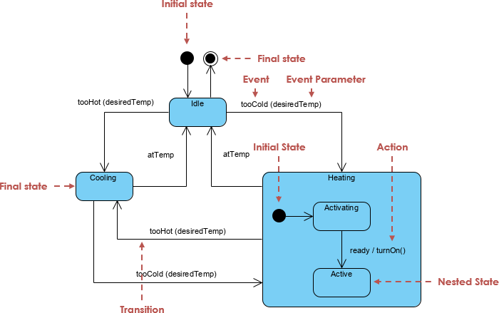
🔑 Key Components of a State Machine Diagram
| Element | Description | Notation |
|---|---|---|
| State | A condition or situation during the object’s lifetime | Rounded rectangle |
| Initial State | Start of the diagram | Black filled circle (●) |
| Final State | End of the lifecycle | Bullseye (⊙) |
| Transition | Movement from source to target state | Arrow with label: trigger [guard] / effect |
| Entry/Exit Actions | Executed upon entering/leaving a state | entry / action(), exit / cleanup() |
| Do Activity | Ongoing activity while in state | do / monitor() |
| Self-Transition | Loop back to same state | Arrow pointing to itself |
| Composite State | State with internal substates | Nested rectangle with region |
| History State | Resume last active substate | H or H* |
| Fork/Join | Split or merge concurrent paths | Thick bar (` |
| Choice/Junction | Conditional branching | Diamond (◇) or filled circle (●) |
🎯 Practical Example: Online Shopping Order Lifecycle
Let’s model the lifecycle of an online order using a UML state machine diagram.
📌 Requirements
-
Order starts as
Pending. -
Transitions to
Paidwhen payment is received. -
If not paid within 48 hours, transitions to
Cancelled. -
Once paid, moves to
Shippedon dispatch. -
From
Shipped, can go to:-
Deliveredon confirmation -
Returnedif customer requests return
-
-
Cancelledstate is reachable from any state before delivery. -
Include
entry,exit, anddoactions where applicable.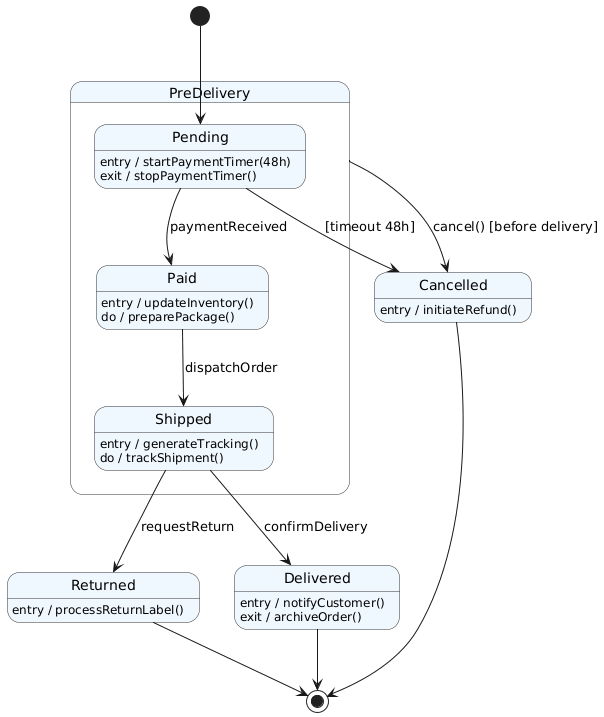
🔄 How AI Accelerates State Diagram Creation
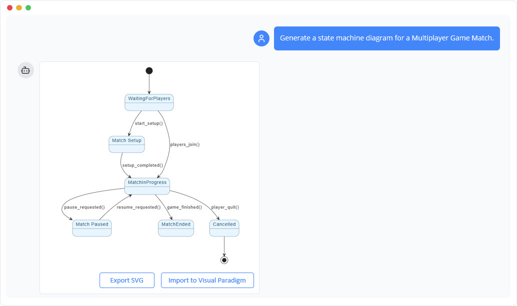
Creating such diagrams manually is time-consuming and error-prone. Enter Visual Paradigm AI, an AI-powered modeling platform that transforms natural language into professional UML diagrams in seconds.
✅ How It Works:
-
Text-to-Diagram Instantly
-
Prompt:
“Create a UML state machine diagram for an online order: starts in Pending, transitions to Paid on payment received, then to Shipped on dispatch, Delivered on receipt confirmation, or Cancelled after 48 hours without payment. Add entry/exit actions and history state if needed.”
-
Result: A fully structured, visually balanced, UML-compliant diagram with proper transitions, guards, and actions—generated in under 30 seconds.
-
-
Iterative Refinement via Chat
-
Refine with:
“Add a deep history state to resume the last active substate in Shipped after a system restart.”
-
AI updates the diagram automatically, adding
H*and correct concurrent regions.
-
-
Export & Integrate
-
Export as PNG/SVG/PDF
-
Integrate with code generators (Java, C++, etc.)
-
Use in documentation, architecture reviews, or agile planning.
-
🛠️ Why Use Visual Paradigm (2026)?
| Feature | Benefit |
|---|---|
| AI Diagram Generator | Turn plain English into UML diagrams instantly |
| AI Chatbot | Ask questions, refine logic, fix inconsistencies |
| Auto-layout & Alignment | Clean, professional visual output |
| Cross-Platform | Desktop, Online, Community Edition (free tier) |
| Round-Trip Engineering | Generate code from diagrams and update diagrams from code |
✅ Ideal for beginners learning UML, developers designing complex workflows, and enterprise architects modeling business lifecycles.
📌 Conclusion
UML State Machine Diagrams are indispensable for modeling dynamic, event-driven systems with clear lifecycle phases. Whether you’re designing an e-commerce order flow, a microwave oven control system, or a traffic light controller, state diagrams provide clarity, reduce errors, and improve communication.
With tools like Visual Paradigm’s AI-powered modeling platform, generating accurate, production-ready state diagrams is no longer a manual chore—it’s a conversational process.
🚀 Start modeling today:
Visit online.visual-paradigm.com or use the AI chatbot at chat.visual-paradigm.com
Try the free Community Edition to generate your first state machine from a simple prompt.
Empower your design. Accelerate your workflow. Model with AI.
Articles and resources:
- Mastering State Diagrams with Visual Paradigm AI: A Guide for Automated Toll Systems: This guide demonstrates how to use AI-enhanced state diagrams to model and automate the complex logic required for toll system software.
- Definitive Guide to UML State Machine Diagrams with AI: This resource provides a detailed look at using AI-powered tools to accurately model object behavior with UML state machine diagrams.
- Interactive State Machine Diagram Tool: A specialized web-based tool for creating and editing state machine diagrams that leverages GenAI capabilities for real-time behavior modeling.
- Generating Source Code from State Machines in Visual Paradigm: This technical guide provides instructions on generating implementation code directly from state machine diagrams to execute state-driven logic.
- Visual Paradigm – UML State Machine Diagram Tool: An overview of a cloud-based interface designed for architects to build, edit, and export precision state machine models.
- 3D Printer State Machine: A Comprehensive Step-by-Step Guide: A walkthrough of the state machine concept as applied to 3D printing systems, explaining their operational logic and automation paths.
- State Diagram Quick Tutorial: Master UML State Machines in Minutes: A beginner-friendly tutorial for mastering UML state machines, covering core concepts and modeling techniques within Visual Paradigm.
- Visualizing System Behavior: A Practical Guide to State Diagrams with Examples: An analysis of how state diagrams provide an intuitive visualization to identify potential system issues early in the design process.
- Creating State Machine Diagrams in Visual Paradigm: Official documentation detailing how to design and implement system behavior modeling using state machine diagrams.
- Visual Paradigm AI Suite: A Comprehensive Guide to Intelligent Modeling Tools: This overview details how the platform’s AI Chatbot supports technical modeling, including state machines and other behavioral diagrams, within the modeling environment.
