The Technology Layer describes system software applications and infrastructure. Wherever applicable, the ArchiMate language draws analogies with the Business and Application Layers. Technology Layer elements are typically used to model an enterprise’s technical architecture, describing the structure and behavior of the enterprise’s technology infrastructure.
Active Structure Elements
The primary active structure element in the Technology Layer is the Node. This element is used to model structural entities at this layer and has the following characteristics:
- It is used to model application servers, database servers, or client workstations.
- It is typically a combination of hardware devices and system software that together provide a complete execution environment.
- It can be composed of sub-nodes.
- Nodes can be interconnected via communication paths.
- Artifacts can be assigned to (i.e., deployed on) nodes.
- Artifacts deployed on a node can be drawn inside the node or connected to it via an assignment relationship.
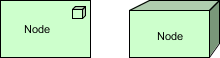
Node Concept Notation
A Node is an active processing element defined as a computational resource upon which artifacts can be stored or deployed for execution.
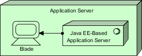
Node Concept Example
In the ArchiMate diagram below, you see an Application Server node composed of a blade device and Java EE-based application server system software.
The name of a node is best a noun.
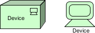
Device Concept Notation
A Device is a specialization of a node representing a physical resource with processing capability. It is typically used to model hardware systems such as mainframes, PCs, or routers.
A Device is defined as a hardware resource on which artifacts can be stored or deployed for execution, with the following characteristics:
- Devices, together with system software, form part of a node.
- Devices may be composite; i.e., composed of sub-devices.
- Devices can be interconnected via networks.
- Artifacts can be assigned to (i.e., deployed on) devices.
- System software can be assigned to devices.
- A device can be composed of sub-devices.
- A node can contain one or more devices.
- The name of a device is best a noun referring to the type of hardware; e.g., “IBM Mainframe.”
- Different icons can be used to distinguish device types, such as mainframes and personal computers.
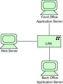
Device Concept Example
The ArchiMate diagram below shows an example of multiple servers modeled as devices, interconnected via a Local Area Network (LAN).
System Software Concept Notation
System Software represents the software environment for a specific type of component or object, on which artifacts in the form of components and objects are deployed.
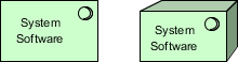
System Software is a specialization of a node used to model the software environment in which artifacts run, with the following characteristics:
- System Software can represent, for example, operating systems, JEE application servers, database systems, workflow engines, or COTS software such as ERP or CRM packages.
- System Software may contain other system software; e.g., an operating system containing a database.
- System Software combined with devices representing the hardware environment forms a generic node.
- System Software can be assigned to devices.
- The name of system software is best a noun referring to the type of execution environment; e.g., “JEE Server.”
- Artifacts can be assigned to (i.e., deployed on) system software.
- A node can contain system software.
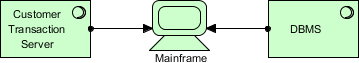
System Software Concept Example
In the ArchiMate diagram below, we see a mainframe device that deploys two system software environments: a Customer Transaction Server and a Database Management System (DBMS).
Technology Interface Concept Notation
A Technology Interface is defined as a point of access where technology services provided by a node can be accessed by other nodes and application components.
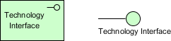
A Technology Interface specifies how the technology services of a node can be accessed by other nodes through the interface provided, with the following characteristics:
- Technology interfaces expose technology services to the environment.
- A technology interface specifies a contract that the realizing component must fulfill.
- Technology interfaces can become part of a node through composition.
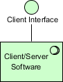
Technology Interface Concept Example
In the model below, we see an exposed client technology interface that is part of the client/server system software.
The name of a technology interface is best a noun.
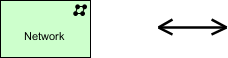
Network Concept Notation
A Network is defined as the medium for communication between two or more devices.
A Network represents the physical communication infrastructure and has the following characteristics:
- It can include one or more fixed or wireless network links.
- The most basic network is a single link between two devices.
- Networks have properties such as bandwidth and latency.
- It embodies the physical realization of logical communication paths between nodes.
- A network connects two or more devices.
- A network realizes one or more communication paths.
- A network can be composed of sub-networks.
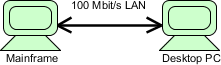
Network Concept Example
In the model below, a 100 Mb/s LAN network connects host and PC devices.
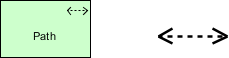
Communication Path Concept Notation
A Communication Path is defined as a link between two or more nodes along which they can exchange data.
- Communication paths are used to model logical communication relationships between nodes and have the following characteristics:
- They are realized by one or more networks representing physical communication links.
- Communication properties of the path (e.g., bandwidth, latency) are typically aggregated from the underlying networks.
- A communication path connects two or more nodes.
- A communication path is realized by one or more networks and is atomic.
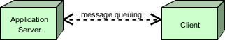
Communication Path Concept Example
In the ArchiMate diagram below, we see a communication path “Message Queue” between an application server and a client.
Behavior Concepts
Behavior elements in the Technology Layer are similar to those in other layers.
They can be distinguished between external behavior aspects of nodes in the form of technology services, and internal behavior of those nodes; i.e., the technology functions that realize these services.
Technology Function Concept Notation
A Technology Function describes the internal behavior of a node and represents a collection of technology behavior that a node can perform.
A technology function abstracts from its realization, and only the necessary behavior is specified. It has the following characteristics:
- Technology functions can realize technology services.
- Technology functions can be served by technology services of other technology functions.
- Technology functions can access technology objects.
- A node can be assigned to a technology function (meaning the node performs the technology function).
- The name of a technology function is best a verb ending in “-ing.”
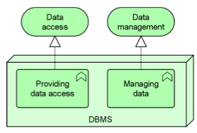
Technology Function Concept Example
In the ArchiMate diagram below, the Database Management System (DBMS) node performs two infrastructure functions: Provide Data Access (realizing Data Access Service for application software) and Manage Data (realizing Data Management Service for database administration).
Technology Process Concept Notation
A Technology Process describes the internal behavior of a node. A technology process represents a sequence of technology behaviors that together achieve a specific result. If its behavior is externally exposed, this is done through one or more technology services.
A technology process has the following characteristics:
- A technology process can realize technology services.
- A technology process abstracts from its realization. Only necessary behavior is specified.
- It can use technology objects as input, use or transform them, and produce other technology objects as output.
- Other technology services may serve (be used by) the technology process.
- A technology process can access technology objects.
- A node can be assigned to a technology process, meaning the node performs the process.
- The name of a technology process should clearly identify a sequence of technology behavior; e.g., “System Startup Sequence” or “Replicate Database.”
Technology Service Concept Notation
A Technology Service represents explicitly defined exposed technical behavior.
A technology service exposes the functionality of a node to its environment. This functionality can be accessed through one or more technology interfaces and has the following characteristics:
- Technology services are realized by technology functions or processes.
- From the environment’s perspective, a technology service should be meaningful.
- It should provide a unit of behavior useful in itself to its users, such as application components and nodes.
- Technology services can serve application components or nodes.
- Technology services may require, use, and produce artifacts, e.g., files containing messages.
- Technology services may be composed of sub-services.
- Technology services may include messaging, storage, naming, and directory services.
- The name of a technology service is best a verb ending in “-ing”; e.g., “Messaging.” Names explicitly including the word “service” can also be used.
Technology Layer Example
The example below shows a technology event Database Update triggering a technology process Remote Data Replication, which is served by the technology service Replicate Database Updates.
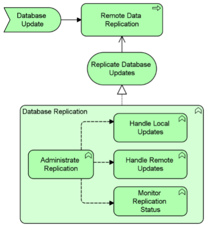
This technology service is realized by a technology function Database Replication, which consists of four additional technology functions:
- Manage Replication
- Process Local Updates
- Process Remote Updates
- Monitor Replication Status
There is an information flow from the Manage Replication technology function to the other three technology functions.
Technology objects model passive structure elements that are used and processed by the infrastructure. Technology objects represent “physical” objects manipulated by the enterprise infrastructure. Technology objects are abstract elements; i.e., they are not instantiated in the model but serve as generic types of things operated on at the technology layer. This can include artifacts (e.g., files) and physical materials.
Artifact Concept Notation
The Artifact element is taken from UML. An artifact is a piece of data produced or used during software development or through the deployment and operation of a system. They can be deployed on a node.
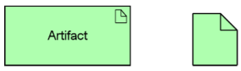
It is represented in the form: artifact: e.g., file for a data object.
Artifact Concept Example
In this example, a Web Archive artifact (which can realize an application component) is composed of two other artifacts:
- Database Access Java Archive
- Business Logic Java Archive
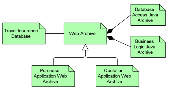
Two specializations of the Web Archive artifact are:
- Purchase Application Web Archive
- Quote Application Web Archive
A Travel Insurance Database artifact (which can realize a data object) is associated with the Web Archive artifact.
