Introduction: The C4 Model and Its Core Strengths
The C4 model has revolutionized how software architects document and communicate system design. By breaking down architecture into —it provides a clear, scalable, and audience-appropriate way to describe software structure.
However, architecture documentation is not just about static structure. It must also . This is where Supporting Diagrams come into play. These diagrams complement the core C4 views, ensuring that architects can tell a complete story—whether for stakeholders, developers, or operations teams.
What Are Supporting Diagrams?
Supporting Diagrams in the C4 model are specialized views that address dimensions not covered by the core structural diagrams. They provide context, clarify interactions, and map software to real-world infrastructure.
Key Supporting Diagrams and Their Focus Areas
| Diagram Name | Focus Area | Why It Supplements C4 |
|---|---|---|
| System Landscape Diagram | Portfolio and Enterprise Scope | Provides a higher-level view than the Context Diagram, mapping all systems in an organization. |
| C4 Deployment Diagram | Infrastructure and Operations | Maps software containers onto physical or cloud infrastructure, showing where the system runs. |
| C4 Dynamic/Sequence Diagrams | Runtime Behavior | Illustrates interaction flows between containers or components for specific use cases. |
When and Why: Integrating Supporting Diagrams into the Workflow
The decision to use a supporting diagram depends on the audience and the story the architect needs to tell. Here’s how and when to use each type:
1. System Landscape Diagram: Setting Organizational Scope
What It Is
The System Landscape Diagram shows all major software systems in an organization, their relationships, and their categorization (e.g., internal vs. external). It sits at a higher level than the System Context Diagram, providing a portfolio-wide view.
When to Use It
- At the beginning of documentation for large organizations or teams managing multiple applications.
- When communicating with high-level business leaders who need a global overview.
Why It’s Needed
- Provides insight into the full scope of systems managed by the organization.
- Helps stakeholders understand dependencies, ownership, and integration points across the portfolio.
2. Deployment Diagram: Mapping Software to Hardware
What It Is
The C4 Deployment Diagram maps containers (from Level 2) onto deployment nodes—physical or virtual infrastructure such as servers, VMs, or cloud environments. It clarifies where each part of the system runs and how it communicates.
When to Use It
- Once the Container architecture (Level 2) is finalized.
- Essential for DevOps, operations, and security teams.
Why It’s Needed
- Shows where containers and databases physically live, aiding operational planning.
- Strengthens incident response by providing a clear operational map.
3. Dynamic and Sequence Diagrams: Illustrating Flow and Interaction
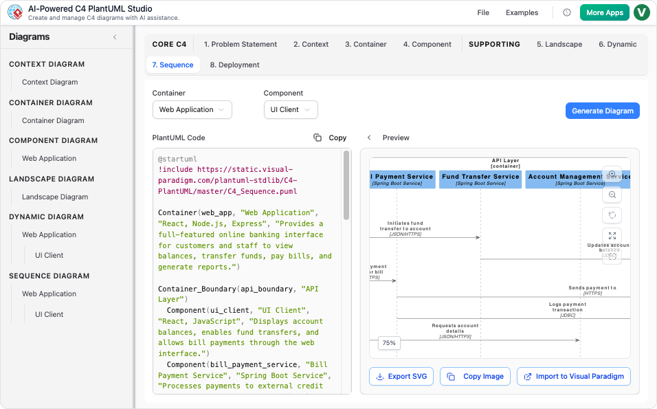
What It Is
The C4 Dynamic Diagram shows a sequence of interactions between containers or components, demonstrating how a specific feature or use case flows through the system. The Sequence Diagram uses UML notation to show the precise ordering of messages over time.
When to Use It
- When documenting complex or critical use cases.
- Most useful for technical implementers (engineers) who need to understand runtime behavior.
Why It’s Needed
- Reveals how the system achieves a specific use case step-by-step.
- Relies on the structural definition of participants (from Levels 2 and 3).
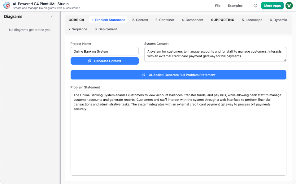
How: Seamless Integration via AI Tools
Creating and maintaining these diagrams manually can be time-consuming. AI-powered tools like :
Instant Generation
- The AI can instantly create any of the six C4 diagrams, including Landscape, Dynamic, and Deployment views, from a simple text description.
Consistent Output
- Using PlantUML, the AI generates structurally consistent diagrams that align with the C4 hierarchy.
Conversational Refinement
- Teams can refine diagrams by issuing commands like:
- “Add a new server.”
- “Replace a database.”
- “Show multiple container replicas.”
- .
Conclusion: A Complete Picture of Software Architecture
The C4 model’s core diagrams provide a structured, hierarchical view of software architecture. However, Supporting Diagrams—such as the System Landscape, Deployment, and Dynamic Diagrams—fill critical gaps by addressing organizational scope, runtime behavior, and infrastructure.
By integrating these diagrams into the workflow, architects can:
- Communicate effectively with stakeholders at all levels.
- Clarify operational realities for DevOps and security teams.
- Document complex interactions for developers.
With AI-powered tools, creating and maintaining these diagrams becomes faster, more consistent, and more collaborative, ensuring that architecture documentation remains accurate, useful, and up-to-date.
Final Thought: The Power of a Complete Story
. Supporting Diagrams ensure that no part of the story is left untold.
-
Title URL C4-PlantUML Studio | AI-Powered C4 Diagram Generator Visit AI-Powered C4 Diagram Generator | Create Architecture Diagrams from Text Visit C4 Component Diagram: A Definitive Guide to Your Code’s Internal Structure with AI Guide C4 Container Diagram: A Definitive Guide to Visualizing Your Software’s Building Blocks with AI Guide C4 Deployment Diagram Visit C4 System Context Diagram: A Definitive Guide to Seeing the Big Picture with AI Guide Generate the Complete C4 Model Instantly with Visual Paradigm’s AI Diagram Generator Updates The Ultimate AI C4 Diagram Tool & Modeling Software Visit New: Full C4 Model Support Added to Visual Paradigm Desktop Release C4 Diagram Tool & Modeling Software Visit
