


Modeling Reactive Business Processes with UML and Visual Paradigm AI
1. Introduction
In modern software development, UML State Machine Diagrams (also known as state diagrams) are essential for modeling the dynamic behavior of systems — especially those governed by a sequence of conditions, events, and time-based decisions.

This case study presents a comprehensive, real-world application of UML State Machine Diagrams to model the lifecycle of an e-commerce order, from creation to final resolution (delivery, return, or cancellation). The diagram is implemented using PlantUML syntax, then analyzed and enhanced using Visual Paradigm’s AI Diagram Generator, showcasing how AI-powered modeling accelerates design, improves clarity, and ensures correctness.
✅ Objective: To demonstrate the full lifecycle of an order using UML state machine concepts, with automated generation and refinement via AI.
🎯 Audience: Software architects, developers, business analysts, students, and technical product managers.
2. Domain Overview: E-Commerce Order Processing
An e-commerce order must progress through multiple stages, each involving distinct business logic, user interactions, system actions, and time constraints. The key challenge lies in managing:
-
Time-sensitive behaviors (e.g., 48-hour payment window)
-
Cross-cutting concerns (e.g., cancellation at any pre-delivery stage)
-
Conditional transitions (e.g., only after shipping can return be requested)
-
Clear separation of concerns (pre-delivery vs. post-delivery states)
Key Requirements
| Feature | Description |
|---|---|
| Initial state | Pending — Order created, awaiting payment |
| Payment timeout | Auto-cancel after 48 hours if not paid |
| Pre-delivery cancellation | Can be canceled anytime before dispatch |
| Post-delivery return | Only possible after delivery |
| Final states | Delivered, Cancelled, Returned |
| Entry/Do/Exit actions | Each state has specific behaviors |
3. UML State Machine Concepts Applied
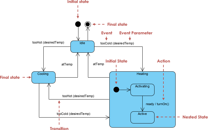
Core Elements Used
| Element | Description | Example from Diagram |
|---|---|---|
| State | A condition during which an object exists | Pending, Paid, Shipped, Delivered |
| Initial State | Start of the lifecycle ([*]) |
[*] → Pending |
| Final State | Termination point (→ [*]) |
All end states lead to [*] |
| Transition | Change between states triggered by an event | Pending → Paid : paymentReceived |
| Guard (Condition) | Restricts when a transition occurs | [timeout 48h] |
| Entry Action | Executed when entering a state | entry / startPaymentTimer(48h) |
| Exit Action | Executed when exiting a state | exit / stopPaymentTimer() |
| Do Activity | Ongoing action while in state | do / preparePackage() |
| Composite State | Group of sub-states with shared behavior | PreDelivery containing Pending, Paid, Shipped |
| Global Transition | Arises from a composite state boundary | PreDelivery → Cancelled : cancel() |
4. Step-by-Step Design Process
Step 1: Identify the Lifecycle Scope
Entity:
Orderin an e-commerce system
Scope: From order creation to final closure (delivered, returned, or canceled).
Step 2: List and Categorize States
We identify 6 core states, grouped into composite regions:
| State | Category | Description |
|---|---|---|
Pending |
Pre-Delivery | Waiting for payment |
Paid |
Pre-Delivery | Payment received; inventory reserved |
Shipped |
Pre-Delivery | Order dispatched; tracking generated |
Delivered |
Post-Delivery | Customer received goods |
Cancelled |
Final | Order aborted before delivery |
Returned |
Final | Goods returned by customer |
⚠️ Note:
Delivered,Cancelled, andReturnedare final states, meaning no further transitions occur.
Step 3: Create Composite State – PreDelivery
The PreDelivery composite state contains all states where the order has not yet been shipped. This allows for a global cancellation transition from any pre-delivery state.
state "PreDelivery" as PreDelivery {
    state "Pending" as Pending
    state "Paid" as Paid
    state "Shipped" as Shipped
}
This enforces consistency in behavior across sub-states and enables shared transitions (e.g., cancellation).
Step 4: Define Transitions & Triggers
| Transition | Trigger | Guard / Condition | Action |
|---|---|---|---|
Pending → Paid |
paymentReceived |
— | updateInventory() |
Paid → Shipped |
dispatchOrder |
— | generateTracking() |
Shipped → Delivered |
confirmDelivery |
— | notifyCustomer() |
Shipped → Returned |
requestReturn |
— | processReturnLabel() |
Pending → Cancelled |
timeout 48h |
After 48 hours | Auto-cancel |
PreDelivery → Cancelled |
cancel() |
[before delivery] |
initiateRefund() |
✅ Guard:
[before delivery]ensures cancellation is only allowed pre-shipment.
🕒 Time Event:[timeout 48h]is a time-based trigger, not a guard — valid forPending.
Step 5: Add Entry, Do, and Exit Actions
Each state has behavioral actions defined:
| State | Entry Action | Do Action | Exit Action |
|---|---|---|---|
Pending |
startPaymentTimer(48h) |
— | stopPaymentTimer() |
Paid |
updateInventory() |
preparePackage() |
— |
Shipped |
generateTracking() |
trackShipment() |
— |
Delivered |
notifyCustomer() |
— | archiveOrder() |
Cancelled |
initiateRefund() |
— | — |
Returned |
processReturnLabel() |
— | — |
💡 These actions represent system behavior and help define when and how operations are performed.
Step 6: Define Final States
All end states (Delivered, Cancelled, Returned) lead to the final state [*], indicating the completion of the order lifecycle.
Delivered --> [*]
Cancelled --> [*]
Returned --> [*]
This allows for multiple exit paths, depending on business rules.
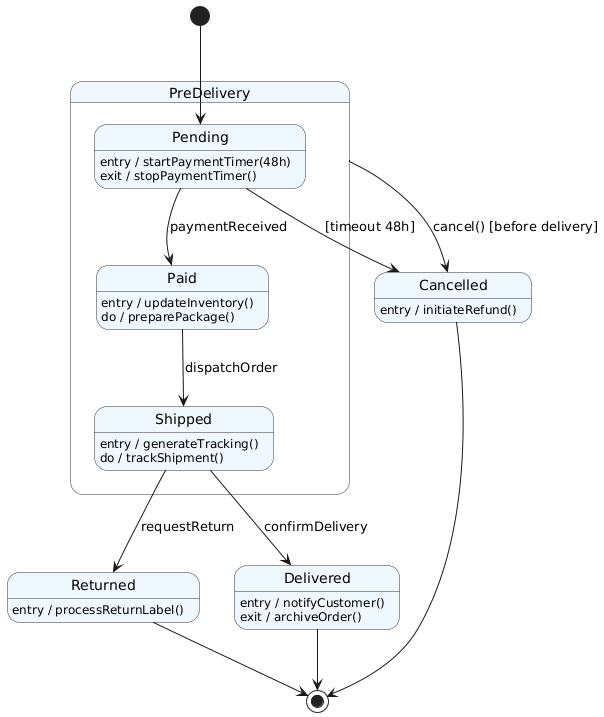
5. Complete PlantUML Code & State Machine Diagram
@startuml
skinparam shadowing false
skinparam state {
    BackgroundColor #F0F8FF
    BorderColor #333333
}

[*] --> Pending

state "PreDelivery" as PreDelivery {
    state "Pending" as Pending {
        Pending : entry / startPaymentTimer(48h)
        Pending : exit / stopPaymentTimer()
    }
    state "Paid" as Paid {
        Paid : entry / updateInventory()
        Paid : do / preparePackage()
    }
    state "Shipped" as Shipped {
        Shipped : entry / generateTracking()
        Shipped : do / trackShipment()
    }

    Pending --> Paid : paymentReceived
    Paid --> Shipped : dispatchOrder
}

PreDelivery --> Cancelled : cancel() [before delivery]

Shipped --> Delivered : confirmDelivery
Shipped --> Returned : requestReturn

state "Delivered" as Delivered {
    Delivered : entry / notifyCustomer()
    Delivered : exit / archiveOrder()
}

state "Cancelled" as Cancelled {
    Cancelled : entry / initiateRefund()
}

state "Returned" as Returned {
    Returned : entry / processReturnLabel()
}

Pending --> Cancelled : [timeout 48h]

Delivered --> [*]
Cancelled --> [*]
Returned --> [*]
@enduml
✅ Best Practices Applied:
Clear visual hierarchy via
stateblocksSemantic labels for events and actions
Use of
skinparamfor consistent stylingAvoided redundant or ambiguous transitions
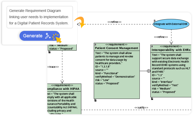
6. Visual Paradigm AI Diagram Generator: Automating the Process
Creating such a diagram manually in PlantUML requires deep syntax knowledge and careful layout tuning. Visual Paradigm’s AI Diagram Generator transforms this into a natural language workflow.
How AI Automates Diagram Creation
Input Prompt (Natural Language)
“Create a UML state machine diagram for an e-commerce order with the following states: Pending (with 48-hour payment timeout leading to cancellation), Paid, Shipped, Delivered, Cancelled, and Returned. Include a composite state for pre-delivery phases. Add entry, do, and exit actions: startPaymentTimer(48h) on Pending entry, updateInventory() on Paid entry, generateTracking() on Shipped entry, notifyCustomer() on Delivered entry, initiateRefund() on Cancelled entry, processReturnLabel() on Returned entry. Add global cancellation transition from PreDelivery to Cancelled. Define transition from Pending to Cancelled on timeout. Make Delivered, Cancelled, and Returned final states.”
AI Output (Automated)
-
Instant generation of a complete, well-formatted UML state diagram
-
Automatic grouping into composite state
PreDelivery -
Smart placement of transitions and actions
-
Visual feedback with color coding and icons
-
Editable model (not just an image)
Iterative Refinement via Chat
User: “Make the 48-hour timeout explicit as a time event.”
AI: Updates the transition toPending --> Cancelled : [timeout 48h]
User: “Add a note explaining that cancellation is only allowed before delivery.”
AI: Adds a note near thePreDelivery → Cancelledtransition.
User: “Export this diagram as PlantUML code.”
AI: Generates the full code block with proper formatting.
7. Advantages of Using AI for State Diagram Design
| Feature | Manual PlantUML | AI-Powered (Visual Paradigm) |
|---|---|---|
| Learning Curve | High (syntax-heavy) | Low (natural language input) |
| Time to Generate | 15–30 minutes | < 2 minutes |
| Error-Prone | Yes (typos, missing states) | No (AI validates structure) |
| Layout & Readability | Manual adjustment needed | Auto-layout with visual clarity |
| Integration | Standalone code | Embedded in full model (with use cases, sequence diagrams) |
| Export Options | PlantUML, PNG, SVG | PlantUML, PDF, code generation (Java/Python), etc. |
| Iterative Refinement | Tedious | Conversational (via chat) |
✅ Ideal for: Rapid prototyping, academic projects, agile teams, domain-driven design (DDD), and documentation.
8. Business and Technical Benefits
✅ For Business Analysts
-
Clearly visualize business rules (e.g., “Order must be paid within 48h”)
-
Communicate workflows to stakeholders using diagrams, not code
-
Validate process logic before development begins
✅ For Developers
-
Generate state pattern code templates (Java, Python, C#) directly from the diagram
-
Implement event-driven architecture with well-defined state transitions
-
Reduce bugs due to missing edge cases (e.g., unhandled timeouts)
✅ For QA & Testing
-
Use diagram to generate test cases (e.g., “test payment timeout”)
-
Ensure full state coverage in automated testing
✅ For Documentation
-
Generate interactive, updatable technical documentation
-
Include in product requirement documents (PRDs) or API specifications
9. Conclusion: From Manual to Intelligent Modeling
The e-commerce order lifecycle serves as a powerful real-world example of how UML State Machine Diagrams can model complex, reactive business processes. While PlantUML provides a robust way to define and export diagrams, Visual Paradigm’s AI Diagram Generator revolutionizes the design workflow by:
🔹 Reducing effort from hours to seconds
🔹 Eliminating syntax errors
🔹 Ensuring accuracy and compliance
🔹 Enabling intelligent iteration
This case study demonstrates that modern tools are not just about drawing diagrams, but about designing systems — one natural language prompt at a time.
10. Final Recommendations
-
Use PlantUML for lightweight, version-controlled diagrams.
-
Leverage AI tools (like Visual Paradigm AI) for rapid prototyping and team collaboration.
-
Always validate transitions with guards, actions, and final states.
-
Integrate state diagrams with use case and sequence diagrams for full system modeling.
-
Export to code when building state machine logic in software (e.g., state pattern in Java).
Appendix: Key Takeaways
| Concept | Summary |
|---|---|
| UML State Machine Diagram | Models behavior over time through states and transitions |
| Composite State | Groups related states (e.g., PreDelivery) |
| Entry/Do/Exit Actions | Define behavior at state boundaries |
| Time-Based Events | timeout X triggers auto-transition |
| Global Transitions | Enable cross-cutting behavior (e.g., cancellation) |
| AI Diagram Generation | Turns natural language into accurate UML models |
📌 Final Note:
The future of UML modeling is not just about syntax, but about intention and intelligence. With AI, you don’t just draw a diagram — you define a process, and the tool brings it to life.
🔗 Learn more: www.visual-paradigm.com
🛠 Try AI Diagram Generator Free: chat.visual-paradigm.com
Articles and resources:
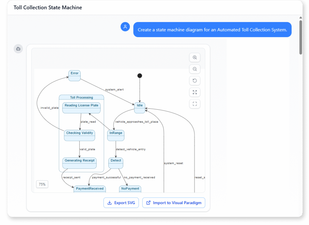
- Mastering State Diagrams with Visual Paradigm AI: A Guide for Automated Toll Systems: This guide demonstrates how to use AI-enhanced state diagrams to model and automate the complex logic required for toll system software.
- Definitive Guide to UML State Machine Diagrams with AI: This resource provides a detailed look at using AI-powered tools to accurately model object behavior with UML state machine diagrams.
- Interactive State Machine Diagram Tool: A specialized web-based tool for creating and editing state machine diagrams that leverages GenAI capabilities for real-time behavior modeling.
- Generating Source Code from State Machines in Visual Paradigm: This technical guide provides instructions on generating implementation code directly from state machine diagrams to execute state-driven logic.
- Visual Paradigm – UML State Machine Diagram Tool: An overview of a cloud-based interface designed for architects to build, edit, and export precision state machine models.
- 3D Printer State Machine: A Comprehensive Step-by-Step Guide: A walkthrough of the state machine concept as applied to 3D printing systems, explaining their operational logic and automation paths.
- State Diagram Quick Tutorial: Master UML State Machines in Minutes: A beginner-friendly tutorial for mastering UML state machines, covering core concepts and modeling techniques within Visual Paradigm.
- Visualizing System Behavior: A Practical Guide to State Diagrams with Examples: An analysis of how state diagrams provide an intuitive visualization to identify potential system issues early in the design process.
- Creating State Machine Diagrams in Visual Paradigm: Official documentation detailing how to design and implement system behavior modeling using state machine diagrams.
- Visual Paradigm AI Suite: A Comprehensive Guide to Intelligent Modeling Tools: This overview details how the platform’s AI Chatbot supports technical modeling, including state machines and other behavioral diagrams, within the modeling environment.
