


A UML State Diagram is a powerful visual tool that models the dynamic behavior of a system by illustrating how it transitions between different states in response to events. It captures the lifecycle of an object or process—showing what it can be in, what triggers a change, and what actions occur during state changes—making it ideal for understanding complex systems like traffic lights, vending machines, login workflows, or game characters. By focusing on states (like “Red,” “Waiting for payment,” or “Jumping”), transitions (driven by events such as “timer expires” or “button pressed”), and conditions (guards), state diagrams provide clarity, prevent logic gaps, and serve as a foundation for both design and code. Whether you’re a beginner learning system modeling or a developer building robust software, mastering state diagrams equips you with the ability to think, design, and communicate system behavior with precision and clarity.
💡 Goal: Learn how to model real-world systems using state machines — from idea to clean, professional-looking diagram.
🔑 Key Concepts You Must Understand First
| Concept | What It Means | Why It Matters |
|---|---|---|
| State | A condition or situation the system is in (e.g., Red, Waiting for coin) |
Shows what’s happening at any moment |
| Event | Something that triggers a change (e.g., Insert coin, timer expires) |
Causes movement between states |
| Transition | An arrow from one state to another | Links states via events |
| Initial State | The starting point (●) | There’s always one |
| Final State | End of the process (○) | Optional — not always needed |
| Guard [condition] | Condition that must be true for the transition to happen | Adds logic (e.g., if enough money?) |
| Action / entry/do | What happens when entering, during, or exiting a state | Adds behavior to states |
📌 Think:
“This system can be in X states.
When Y happens, it moves to Z.”
That’s a state machine!
🛠 Step 0 – Mindset: Ask These Questions
Before drawing anything:
-
What are the clearly different situations this thing can be in?
-
What events (user actions, time, errors) cause changes?
-
Can it be in two states at once? (No → basic state machines are mutually exclusive.)
👉 Example: A light switch is either On or Off. Never both.
🧩 Step 1 – Pick One Concrete Thing to Model
✅ Good beginner choices:
-
Turnstile (locked/unlocked)
-
Traffic light (red/green/yellow)
-
Vending machine
-
Login system
-
Order status:
Created → Paid → Shipped → Delivered
❌ Avoid:
-
“The whole online shop” → too big
-
“The user experience” → too vague
✏️ Start simple. Master the small example first.
📌 Step 2 – List States (Use Nouns or Present Participles)
Write down 4–8 realistic states.
Use adjectives or present participles to make it look like a state:
-
Red -
Green -
Yellow -
Waiting for coin -
Dispensing item -
Preparing -
Payment failed
✅ Tip: If you have more than 10 states → split the system into smaller ones.
🖌 Step 3 – Draw States as Rounded Rectangles
Use rounded rectangles:
[ Red ]
[ Green ]
[ Waiting for coin ]
✅ Tools:
draw.io / diagrams.net (best free choice)
Excalidraw (hand-drawn feel)
PlantUML (text-based → easy to version control)
Lucidchart / Miro
🔷 Step 4 – Add the Initial State (Black Dot)
Draw a filled black circle with an arrow pointing to the first state.
[*] --> Red
The
[*]means “initial state” — it’s the starting point.
➡️ Step 5 – Draw Transitions with Events
For each state, ask:
“What can happen here that makes me leave this state?”
Label arrows with:
event [guard] / action
🔹 Start simple: just
eventorevent / action
Common events:
-
Insert coin -
timer expires -
payment failed -
button pressed -
pedButton -
timeout
✅ Step 6 – Add Final State (Optional)
Use a circle with a thick border for final state.
[Delivered] --> [●]
Not all systems have final states (like traffic lights that run forever).
🔁 Step 7 – Add Realistic Edge Cases
Ask:
-
Can you cancel? → add
Cancel→ back toIdle -
Does time run out? →
timeout→ go back toWaiting -
Can it fail? → add
error→Back to Start -
Can it stay in the same state? → self-transition
Example of self-transition (adding more money):
[Has credit] -- coin inserted --> [Has credit]
🚦 Step 8 – Use Guards for Smart Logic
When the same event leads to different outcomes, use guards.
Example:
If you press
pedButtonduringGreen, but there’s no demand yet → you enterGreen with Ped waiting.
But if demand is already set → you just ignore it.
[Vehicle Green] --> [Vehicle Green] : pedButton / set demand = true
This is a self-transition with action — not a new state.
🎯 Step 9 – Add Entry/Do/Exit Actions (Optional but Powerful)
You can write actions inside the state box:
[Red]
entry / turn red ON
exit / turn red OFF
do / wait 30 seconds
Helps clarify behavior without cluttering transitions.
✅ Step 10 – Final Checklist (Ask Yourself)
| ✅ Check | Why It Matters |
|---|---|
| One initial state? | Must start somewhere |
| All states have outgoing arrows (except final)? | No dead ends |
| No unreachable states? | Every state should be reachable |
| Transitions labeled with events? | Clear cause-and-effect |
| Arrows don’t say “go to X” — the arrow shows direction | Cleaner |
| Cancel / timeout / error paths included? | Real systems fail — prepare for it |
| Diagram fits on screen? | Clean and readable |
📋 Quick Reference: PlantUML Syntax (UML Standard)
| Symbol | Meaning |
|---|---|
[*] |
Initial state |
[*] --> State |
Start from this state |
State --> State |
Transition |
event [guard] / action |
Label on arrow |
state "Name" |
Named state (optional) |
state "X" as X |
Alias for complex names |
note right of State |
Comment box |
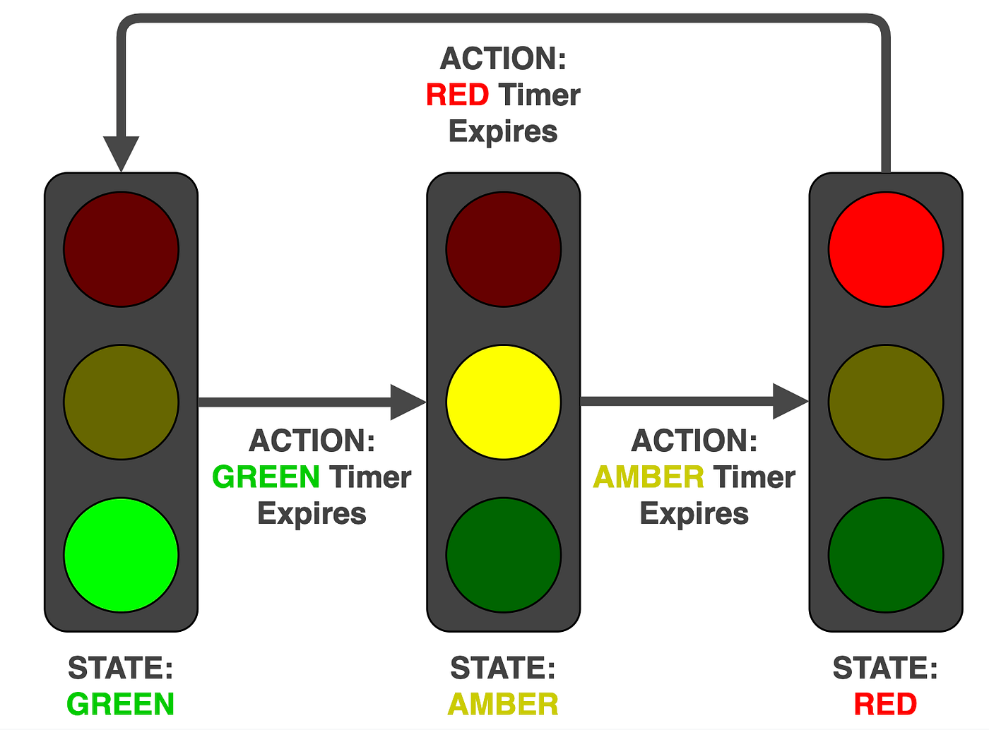
🎯 Example 1: Simple Traffic Light (3-State Cycle)
Perfect for absolute beginners.
🧠 Real-World Use:
-
Basic traffic light cycle: Red → Green → Yellow → Red
✅ States:
-
Red -
Green -
Yellow
🔄 Events:
-
timer expires(after 30s, 25s, 5s)
🛠 PlantUML Code (Copy-Paste Ready):
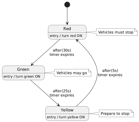
@startuml
skinparam monochrome true
[*] --> Red
Red --> Green : after(30s)\ntimer expires
Green --> Yellow : after(25s)\ntimer expires
Yellow --> Red   : after(5s)\ntimer expires

Red   : entry / turn red ON
Green : entry / turn green ON
Yellow: entry / turn yellow ON

note right of Red
  Vehicles must stop
end note

note right of Green
  Vehicles may go
end note

note right of Yellow
  Prepare to stop
end note
@enduml
✅ How to use:
Go to https://www.plantuml.com/plantuml, paste the code, and press “Generate”.
🖼️ Output: A clean, animated-looking state machine diagram.
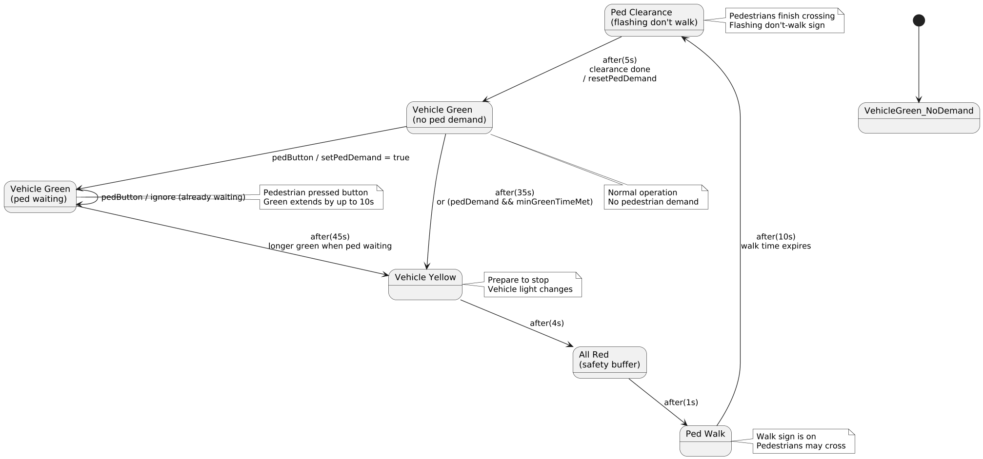
🎯 Example 2: Realistic Traffic Light with Pedestrian Request
The most educational version — introduces guards, self-transitions, and complex logic.
🧠 Real-World Use:
-
Pedestrians press a button to cross.
-
The light waits longer if someone is waiting.
-
After green ends, it goes to yellow → red → walk → flashing don’t walk → back to green.
📌 Key States:
-
VehicleGreen_NoDemand– green, no pedestrian waiting -
VehicleGreen_PedWaiting– green, someone pressed button -
VehicleYellow– yellow light (no walk) -
AllRed– safety buffer (very short) -
PedWalk– walk sign on -
PedClearance– flashing don’t walk (clearing time)
🧩 Key Transitions:
-
pedButton→ if not waiting → set demand -
timer expires→ go to yellow (if green time met) -
pedButtonwhile yellow/red → remember demand -
timerWalk→ go to flashing don’t walk -
timerClearance→ reset and return to green
🚨 Note: This version uses guards and self-transitions, showing why state machines are powerful.
✅ PlantUML Code (Fully Working, Ready to Use):
@startuml
skinparam monochrome true
skinparam shadowing false
skinparam dpi 120

[*] --> VehicleGreen_NoDemand

state "Vehicle Green\n(no ped demand)" as VG_No
state "Vehicle Green\n(ped waiting)"   as VG_Wait
state "Vehicle Yellow"                  as VYellow
state "All Red\n(safety buffer)"      as AllRed
state "Ped Walk"                    as PedWalk
state "Ped Clearance\n(flashing don't walk)" as PedClear

VG_No --> VG_Wait : pedButton / setPedDemand = true
VG_No --> VYellow : after(35s)\nor (pedDemand && minGreenTimeMet)
VG_Wait --> VYellow : after(45s)\nlonger green when ped waiting
VG_Wait --> VG_Wait : pedButton / ignore (already waiting)
VYellow --> AllRed : after(4s)
AllRed --> PedWalk : after(1s)
PedWalk --> PedClear : after(10s)\nwalk time expires
PedClear --> VG_No : after(5s)\nclearance done\n/ resetPedDemand

note bottom of VG_No
  Normal operation
  No pedestrian demand
end note

note right of PedClear
  Pedestrians finish crossing
  Flashing don't-walk sign
end note

note right of VG_Wait
  Pedestrian pressed button
  Green extends by up to 10s
end note

note right of VYellow
  Prepare to stop
  Vehicle light changes
end note

note right of PedWalk
  Walk sign is on
  Pedestrians may cross
end note
@enduml
💡 Why this is better than simple version?
Shows real-world complexity
Demonstrates guards (
if pedDemand)Uses self-transitions (
VG_Wait --> VG_Wait)Models real behavior: green can be extended!
Clear separation of vehicle and pedestrian logic
🎓 Recommended Practice Exercises (Do in Order)
| # | Example | Time | Skills Learned |
|---|---|---|---|
| 1 | Light switch (On ↔ Off) | 5 min | Basic transitions |
| 2 | Turnstile (Locked ↔ Unlocked) | 10 min | Events, guards |
| 3 | Traffic light (3-state cycle) | 10 min | Timers, entry actions |
| 4 | Vending machine (waiting → paying → dispensing) | 15 min | Multiple events, money logic |
| 5 | Login (empty → typing → submitting → success/fail) | 15 min | Error handling, final states |
| 6 | Order status (6 states) | 20 min | Real-life system modeling |
✅ Start with #1–3 on paper or in draw.io. Then use PlantUML for the rest.
🧠 Final Tips for Success
-
Start small — don’t try to include everything at once.
-
Use real names —
Waiting for coin, notState1. -
Label transitions clearly —
button pressed,timeout,payment failed. -
Draw it first by hand — then digitize.
-
Test it mentally: “Can this system get stuck?” → if yes, add a transition.
📌 Summary: Your State Machine Checklist
✅ One [*] (initial state)
✅ Rounded rectangles for states
✅ Arrows for transitions
✅ Events on arrows (after(30s), pedButton)
✅ Guards where needed ([pedDemand])
✅ Self-transitions for repeated actions
✅ Entry/exit actions for behavior
✅ Clean layout, readable font
🎯 Final Words: You’re Now Ready!
You’ve just learned:
-
What a state machine diagram is
-
How to think in states and events
-
How to draw and read them like a pro
-
How to model real systems, like traffic lights
-
How to use PlantUML to write clean, maintainable diagrams
🎉 You’re not just learning UML — you’re learning how to model real systems, one state at a time.
📌 Next Steps (Your Learning Path)
-
Draw the 3-state traffic light by hand — no tools, just paper.
-
Try PlantUML with the code above — see it render.
-
Modify: Change the waiting times. Add “emergency override” state.
-
Try the vending machine → same logic, but with money.
-
Draw your own: A game character (walking → jumping → attacking → dead).
💬 Need help? Try this: “I’m trying to model a [your system] — can you help me make a state machine?”
🙌 Final Thought
🔄 Everything that changes — whether it’s a light, a login, or an order — can be modeled with a state machine.
You don’t need to be a programmer to understand it. You just need to ask: “What can this thing be in, and what makes it change?”
✅ You now know how to create a professional, working state machine diagram — from beginner to confident modeler.
🎉 Happy diagramming!
Let me know if you’d like a printable PDF version, a quiz, or a coding challenge to test your skills.
