


There are two common misunderstanding about use case modeling :
One is that, use case diagram is too simple, as it does not explain anything important and it is not worth drawing.
Another misunderstanding is just opposite to the first one. Some people believe that use case diagram is so powerful that can represent many different aspects of a software, from describing system requirements to modeling the internal behaviors of the system.
So what is use case?
What is use case diagram
Is use case modeling simple or powerful?
A use case is a list of actions or event steps that typically define the interaction between an actor (called an actor in Unified Modeling Language (UML)) and a system to achieve a goal. Actors can be people or other external systems. In systems engineering, use cases are used at a higher level than in software engineering and usually represent task or stakeholder goals.
What is a Use Case Diagram?
A use case diagram is usually simple. It does not show the detail of the use cases:
- It only summarizes some of the relationships between use cases, actors, and systems.
- It does not show the order in which steps are performed to achieve the goals of each use case.
As said, a use case diagram should be simple and contains only a few shapes. If yours contain more than 20 use cases, you are probably misusing use case diagram.
What is Use Case Modeling?
Use case modeling is a simple answer to the question “What does the user (customer) want? It allows you to visually represent what the user wants to achieve by using the final end product, which can be a system, a piece of software, a program, etc. Use case modeling is a useful technique that provides software developers with a solid foundation for developing software systems that meet customer needs.
Although the notation applied in use case diagrams may seem simple and does not convey much detail, the way use cases are collected, organized, and elaborated does greatly influence the direction of the software development lifecycle, and thus the quality of the final software product.
10 Practical Tips for Use Case Modeling
In this article, we will go through ten tips to maximize the effectiveness of drawing use case diagrams. We are not going to explain in detail what a use case is, but will cover some key concepts about UML modeling, use case diagrams and requirements capture.
1. Think from end user’s perspective
It is clear that you need to know users’ expectation in order to build a software system that works, and this principle is particular important in use case modeling. Many people has mistakenly treats use case modeling as a process to model system functions, which can be wrong. To be accurate, use case modeling is a way to model what the users want. Each of the use cases in a use case diagram should yield an observable goal through users’ interaction with the final software or system. Sometimes, a user goal is the same as a system function but this is not always true. For instance, “Login” is a system function but it is definitely not a user goal – No one will start a program, login and go away! So, the more system functions you draw in a use case diagram, the less effective the use case model can be used to express users’ real expectation throughout the entire software development process. Therefore, when you develop a use case model, try to express everything by first thinking from end user’s perspective.
2. Avoid long use case name
If you are reading a use case diagram prepared for an ATM system, which of the following use cases do you want to see in the diagram? “Withdraw Cash” and “Withdraw Cash and Update Balance in Account”. The second use case seems to be more descriptive, right? What about having 50+ different use cases with such a long name? You probably does not want to read the diagram anymore and perhaps your eyes will be in pain.

Use cases with short names
One of the reasons why we need modeling is that we want to understand a complex software system in an easy and simple manner. That’s why the UML has provided us with many different kinds of notations with each of them representing a specific perspective in describing a complete software system. This “spirit” applies to naming use cases as well. If we try to name use cases with detailed description, why don’t we just use a text file instead? In order to make a use case diagram easy to understand, it is important to keep the names of use cases short, yet remain descriptive. Keep the names short and leave the detailed description to the description part of use cases.
3. Actor is a role, not a real person

Actor is a role
Some people try to represent employees in an organization as actors in use case diagram, which end up having a diagram with Peter, Mary, Daisy, etc Remember, an actor represents a unique role that comprises of people, sub-system or whatever entities with unique characteristic and share the same goals and expectations.
4. Model common use case with relationship
![]()
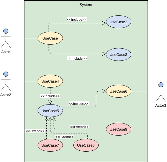
The Include relationship
A use case represents a user goal, which can be achieved by going through a series of steps. When exactly the same steps are found among use cases, you can optionally create a new use case for the common steps and connect it with the use cases that trigger the steps. By using included use case, this makes it clear that the including use cases are indeed sharing the same set of steps as represented by the included use cases with no uncertainty.
5. Model exceptional behavior

The Extend relationship
The extend relationship can be used to specify when and how the behavior of a use case may be triggered by another use case. Extension takes place at extension points defined in extended use case. The extending use case defines the steps that may be executed by the extended use case under specific conditions.
6. Model scenario with flow of events
A use case represents a user goal, which can be achieved by going through a sequence of steps. Some people try to model the steps directly on use case diagram, by connecting actor and use case with many many associations, pretending to be the steps, which is definitely wrong. Instead, the steps of use case can be well described in the use case flow of events editor.

Use case flow of events
The flow of events editor is in tabular form, with each row representing a step of use case. You can write down the steps there, with or without conditional flow. You can also apply formatting to text for emphasizing key ideas.
7. Make good use of stereotype for categorization

Use cases with stereotype applied
Stereotype is a mechanism that allows you to introduce domain specific notation in addition to those standard ones. A stereotype is shown within a pair of guillemets, on top of the name of shape when the stereotype is applied. The proper use of stereotype helps readers to realize the differences of use cases on easier.
8. Model detailed system flow with sequence diagram
Sequence diagram allows you to model the system behavior by representing the communication and interchange of messages between objects over time. But where to begin with? Instead of guessing what interaction to model, you can start by referring to what the user needs, which is exactly what a use case model aimed to present.
We know that every single use case represents a unique user goal. To draw sequence diagram from a use case implies that you are going to model what the computer system should do to fulfill the user. Ideally, there will not be any redundant design as all the sequence diagrams are created from use cases, which represent what the user wants.
9. Apply same width on use cases when appropriate
Since the names of use cases are different in length, it is normal to have the use cases in different width. To make the diagram prettier and easier to read, it would be nice to resize them to the same width.
10. Position actors and use cases in a meaningful way
A use case diagram with randomly placed actors and use cases is definitely a nightmare for readers. One has to examine the diagram carefully in order to find out the information he want from the scattered actors and use cases. It would be nice to place shapes in a discipline manner. You may also group use cases with package shapes if necessary.
References:
