


Designing control logic for autonomous systems requires precision. When engineers move from concept to implementation, the Unified Modeling Language (UML) state machine diagram often serves as the blueprint. However, a disconnect between the diagram and the actual code can lead to catastrophic failures in robotic environments. A robot that hesitates when it should move, or one that enters an infinite loop during a simple task, often stems from fundamental errors in the state machine architecture.
Building reliable embedded software demands more than just drawing boxes and arrows. It requires a deep understanding of execution flow, timing, and resource management. This guide examines the specific pitfalls that compromise robotic state machines. By identifying these structural weaknesses, developers can ensure their systems operate with the stability required for real-world deployment.
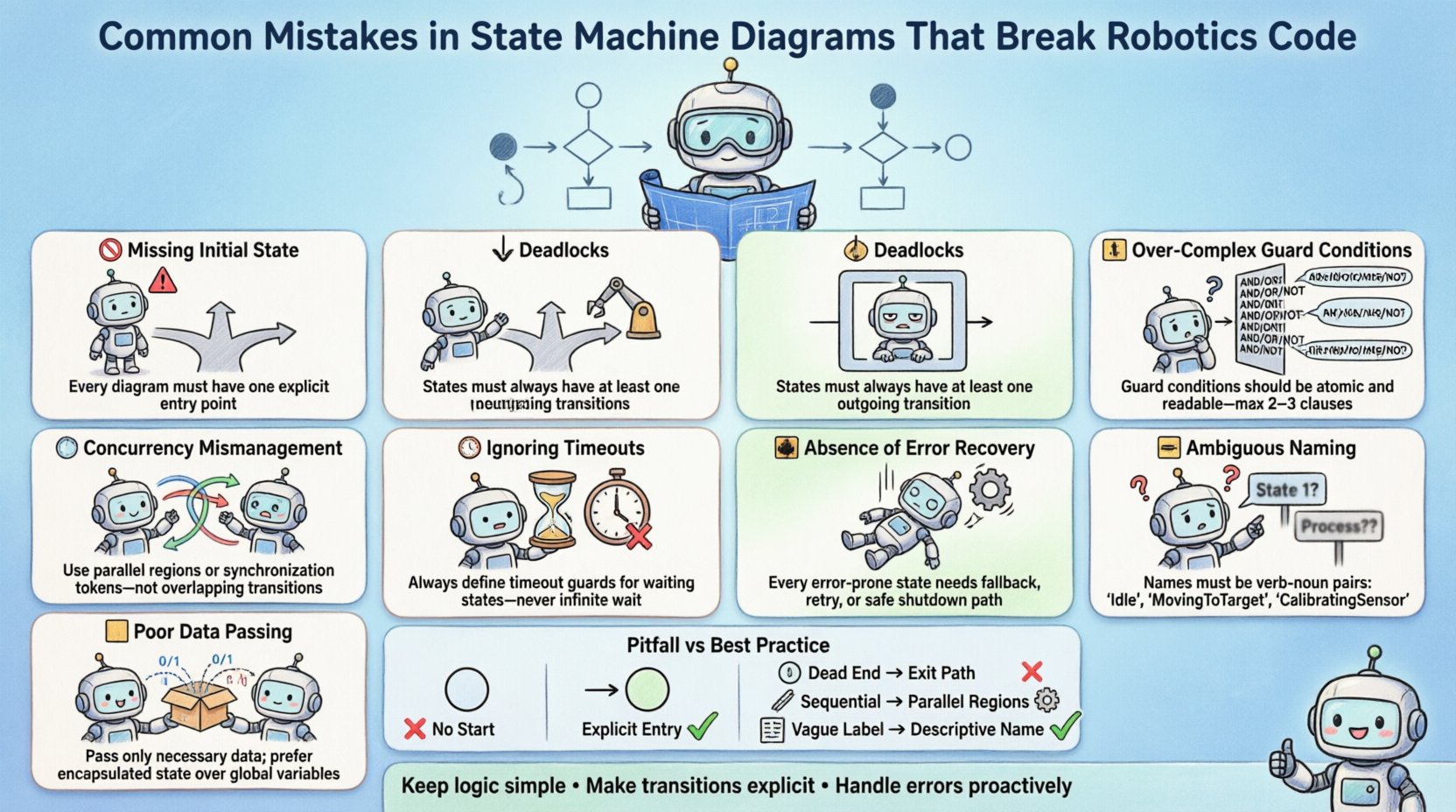
1. 🚫 The Missing Initial State
The foundation of any finite state machine (FSM) is the initial state. This is the entry point where the system begins its operation upon power-up or reset. A common error in diagramming is omitting this starting point or leaving it ambiguous.
When code is generated from a diagram that lacks a defined entry state, the runtime environment often defaults to an arbitrary state. In a robotic context, this means the robot might start in a “Moving” state when it should be in “Idle”. This can cause immediate actuator activation, leading to safety hazards.
- Undefined Start: The code assumes a state exists without verifying it is the correct entry point.
- Power Cycle Issues: On reboot, the robot may retain data from the previous session but fail to reset the control logic.
- Initialization Logic: Without a dedicated initial state, initialization sequences are often scattered across multiple transition functions.
Every robust state machine must explicitly define the entry condition. This ensures that sensors are calibrated, actuators are braked, and the logic controller is ready before the robot accepts external commands.
2. ⏸️ Deadlocks and Missing Transitions
A deadlock occurs when a system enters a state from which no transitions are possible. In a diagram, this looks like a box with no outgoing arrows. In code, this manifests as a hang or a freeze.
Robots operate in dynamic environments. If a sensor fails to report data, the robot must not stop indefinitely. A state machine that waits for a condition that never occurs creates a deadlock. This is particularly dangerous in navigation tasks where a robot might wait for a path to clear that is blocked by an obstacle.
Common causes of deadlocks include:
- Unreachable States: States that are defined in the diagram but never connected to the main flow.
- Missing Default Transitions: Failing to define a “catch-all” transition for unexpected inputs.
- Logical Contradictions: Guard conditions that are mutually exclusive, leaving no path forward.
To prevent this, every state should have a defined exit path. If the expected condition is not met within a specific timeframe, the system should transition to a timeout or error state rather than waiting forever.
3. 🔄 Concurrency Mismanagement
Robots often perform multiple tasks simultaneously. A drone might need to stabilize its flight while scanning for obstacles. A simple sequential state machine cannot handle this. Engineers sometimes attempt to model concurrency by nesting states, but this often leads to complex, hard-to-maintain logic.
True concurrency requires parallel regions within the state machine. If a diagram shows a single flow for parallel tasks, the resulting code will likely execute them one after another. This introduces latency that can be unacceptable for high-speed control loops.
- Interleaved Execution: Sequential processing of parallel tasks causes delays in critical operations.
- Resource Contention: Multiple states trying to access the same hardware resource simultaneously without synchronization.
- State Explosion: Trying to model every combination of parallel tasks results in a combinatorial explosion of states.
Proper modeling involves identifying independent activities and assigning them to distinct parallel regions. This allows the runtime to schedule them efficiently without blocking one another.
4. 🛑 Over-Complex Guard Conditions
Guard conditions are logical expressions that determine if a transition can occur. While essential for control, making these conditions too complex obscures the logic flow. A guard that spans five lines of code is difficult to debug and verify.
In robotics, sensors provide noisy data. A guard condition relying on multiple sensor readings simultaneously is prone to race conditions. If one sensor updates slightly before another, the logic might evaluate differently than intended.
Complex guards lead to:
- Hidden Dependencies: The order of evaluation matters, but is not explicit in the diagram.
- Debugging Difficulty: When a transition fails to trigger, it is hard to determine which part of the condition failed.
- Code Bloat: Complex logic often gets duplicated across multiple transitions.
It is better to simplify guard conditions. Move complex logic into the entry or exit actions of a state. This keeps the transitions clean and the state diagram readable. For example, instead of checking a battery level on every transition, check it once upon entering the “Low Power” state.
5. ⏱️ Ignoring Timeouts and Watchdogs
Real-time systems require time awareness. A state machine that relies solely on event triggers is fragile. What happens if an event never arrives? The robot waits indefinitely.
Implementing timeouts is crucial for resilience. Every state should have a maximum duration it can remain active. If the transition condition is not met, a timer triggers a fallback state.
- Hardware Watchdogs: External mechanisms that reset the system if the software hangs.
- Internal Timers: Logic within the state machine to enforce time limits on specific states.
- Heartbeat Signals: Ensuring the control loop is active and responding.
Without timeouts, a temporary sensor glitch can lock a robot in place. A timeout mechanism ensures the system recovers gracefully and attempts to reset or enter a safe mode.
6. 🚨 Absence of Error Recovery States
Many diagrams focus only on the “happy path”. They show how the robot works when everything goes right. They rarely show how the robot behaves when things break.
Robots operate in unstructured environments. Joints may jam, motors may overheat, or communication may drop. Without explicit error states, the system may crash or behave unpredictably.
A robust state machine includes:
- Safe States: A designated state where the robot stops all motion and waits for intervention.
- Recovery Logic: Steps taken to attempt to reset the system automatically.
- Diagnostic Outputs: Logging specific error codes to help engineers identify the root cause.
Ignoring error states shifts the burden of failure handling to the code generation layer, which often lacks the context to handle edge cases effectively.
7. 📦 Poor Data Passing Mechanisms
Data flows through a state machine via transitions. When a robot moves from “Approaching” to “Grasping”, it needs to pass the target coordinates. If the state machine diagram does not clearly define how data is passed, the code will struggle.
Common issues include:
- Global Variables: Relying on shared memory without synchronization leads to race conditions.
- Missing Parameters: Transitions defined without the necessary data context.
- Data Latency: Passing data that is stale by the time the state is entered.
Parameters should be explicitly defined on transitions. This ensures that the receiving state has the exact information it needs at the moment of entry. It also makes the diagram self-documenting regarding data dependencies.
8. 🏷️ Ambiguous State Naming Conventions
Names in a state machine are the primary interface for debugging. Vague names like “State 1” or “Process” provide no insight into the system’s status. In a complex robot, an engineer needs to look at a log and immediately know what the system is doing.
Good naming conventions should be:
- Descriptive: “Wheel_Motor_On” is better than “Run”.
- Consistent: Use the same verb tense and noun structure across all states.
- Unique: Avoid names that look similar, such as “Error” and “Error_Handler”.
Consistent naming reduces cognitive load when reviewing code or logs. It also helps automated tools generate better documentation and test cases based on the model.
Table: Common Pitfalls vs. Best Practices
| Area | Pitfall | Best Practice |
|---|---|---|
| Entry Point | No initial state defined | Explicit entry point with initialization logic |
| Flow Control | Deadlocks due to missing transitions | Ensure every state has an exit path |
| Parallelism | Sequential processing of parallel tasks | Use parallel regions for independent activities |
| Logic | Complex guard conditions | Move logic to state actions, keep guards simple |
| Timing | No timeouts on waiting states | Implement watchdogs and internal timers |
| Reliability | Missing error states | Define safe and recovery states explicitly |
| Data | Implicit global data sharing | Pass data explicitly via transition parameters |
| Documentation | Ambiguous state names | Use descriptive, consistent naming conventions |
Implementation Considerations
Once the diagram is finalized, the translation to code requires care. The model should drive the implementation, not the other way around. Modifying the code to bypass a state machine constraint often leads to technical debt.
Code generators can help bridge this gap. They ensure that the runtime matches the design exactly. However, relying solely on generation without understanding the underlying logic is risky. Engineers must be able to read the generated code and verify it matches the intent of the diagram.
Testing the State Machine
Unit testing is vital. Each state and transition should be verified independently. Integration testing ensures that state changes do not cause side effects in other parts of the system.
- Transition Testing: Verify that specific inputs trigger the correct state changes.
- State Verification: Ensure the system remains in a state until a valid exit condition occurs.
- Stress Testing: Run the system under load to check for timing issues or race conditions.
Simulation environments allow for safe testing of failure modes. Engineers can introduce sensor failures or communication delays to see how the state machine reacts without risking hardware.
The Cost of Poor Modeling
Fixing a state machine in the diagram is cheap. Fixing it in deployed code is expensive. In robotics, a logic error can mean physical damage to the robot or the environment. It can also mean injury to operators.
Investing time in a rigorous design process pays off in stability. A well-documented state machine serves as a single source of truth for the entire development team. It allows for better collaboration between hardware and software engineers.
Summary of Key Takeaways
Building reliable robotics code starts with a solid model. Avoiding common pitfalls like missing initial states, deadlocks, and poor concurrency handling is essential. Robust error handling and clear data passing mechanisms ensure the system can recover from unexpected conditions.
By adhering to these principles, developers can create state machines that are not just functional, but resilient. The difference between a prototype and a product often lies in the quality of the control logic. Attention to detail in the design phase prevents headaches in the deployment phase.
Keep the logic simple. Make the transitions explicit. Handle errors proactively. These practices form the backbone of dependable robotic systems.
