


Designing reliable embedded software requires precision. At the core of this precision lies the Finite State Machine (FSM). A State Machine Diagram in UML provides a visual representation of system behavior, capturing states, transitions, events, and actions. When implemented correctly, these diagrams serve as the blueprint for robust code generation and verification. However, without strict adherence to structural rules, even the most complex logic can degrade into spaghetti code or unpredictable runtime behavior.
This guide outlines ten critical rules for constructing State Machine Diagrams within embedded contexts. These rules focus on determinism, clarity, and maintainability. By following this checklist, engineers can ensure that the logical flow remains intact from design through deployment.
📋 Understanding the Embedded Context
Embedded systems differ significantly from general-purpose computing environments. They often operate under strict memory constraints, real-time deadlines, and power limitations. A state machine in this environment is not merely a flowchart; it is the runtime controller. If the diagram contains ambiguity, the resulting code may exhibit race conditions, deadlocks, or infinite loops.
A well-structured diagram must answer specific questions before code is written:
- What is the system doing right now?
- What events trigger a change?
- What actions occur during the transition?
- Where does the process end or reset?
The following rules address these questions systematically.
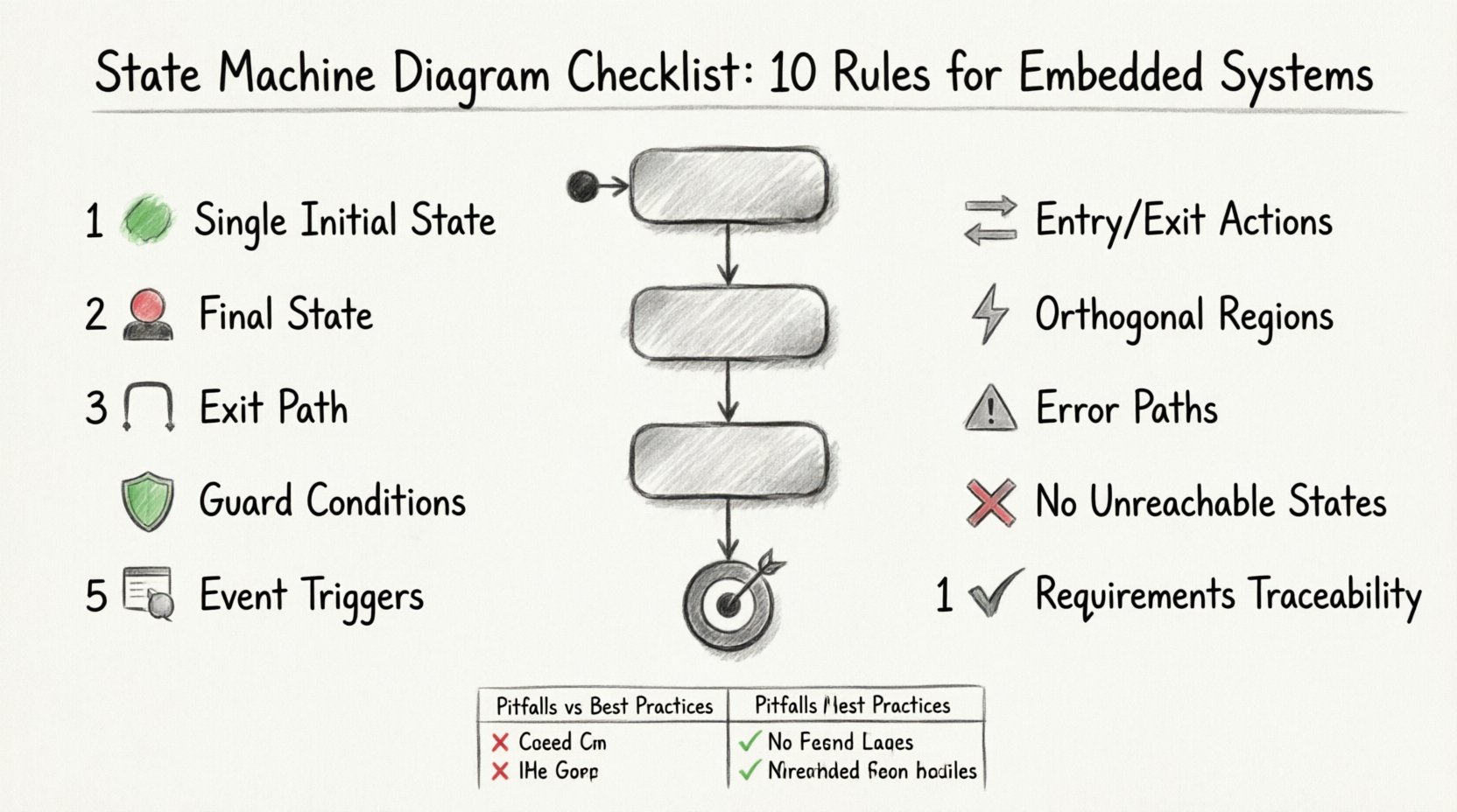
🔟 10 Rules for Logical Flow
1. Define a Single Initial State 🟢
Every valid state machine must begin in one specific location. The initial state acts as the entry point for the system during boot-up or reset. Having multiple starting points creates ambiguity regarding the system’s condition immediately after power-on.
- Rule: Ensure exactly one initial pseudo-state connects to the first concrete state.
- Implication: This guarantees deterministic initialization. The system does not need to guess its starting condition.
- Check: Verify that no other transitions lead into the initial node without a specific reset event.
2. Explicitly Define the Final State 🏁
While embedded systems often run continuously, logical sessions or tasks within the system may have a termination point. A final state indicates the successful completion of a sequence. Without it, the system may hang in a terminal state without signaling completion.
- Rule: Mark the end of a specific workflow with a final state symbol.
- Implication: This allows the system to release resources or notify the upper layers of success.
- Check: Ensure all logical paths eventually converge or terminate explicitly rather than fading into undefined behavior.
3. Ensure Every State Has an Exit Path 🚪
A state that traps the system is a critical failure mode. Unless a state is designed to be a halt state, it must allow the system to leave when an appropriate event occurs. Deadlocks often arise when a state lacks an outgoing transition.
- Rule: Validate that every state possesses at least one outgoing transition.
- Implication: This prevents the system from freezing during operation.
- Check: Review the diagram to confirm no “sink” states exist except for intentional error handling or final states.
4. Use Clear Guard Conditions 🛡️
Transitions are often conditional. Guard conditions specify the boolean logic required for a transition to fire. Vague conditions lead to non-deterministic behavior where the same event might trigger different outcomes based on hidden variables.
- Rule: All transitions must have explicit guards if they are not always active.
- Implication: Guards ensure that state changes occur only when data integrity is verified.
- Check: Avoid internal variable references that are not documented. Keep guards simple and testable.
5. Specify Event Triggers Precisely 📡
Events drive state changes. In embedded systems, these events can be hardware interrupts, software signals, or timeouts. Ambiguous naming leads to confusion during implementation.
- Rule: Name events consistently and map them to specific hardware or software sources.
- Implication: Clear naming reduces errors when mapping the diagram to code.
- Check: Ensure no two transitions from the same state share the same event name without a guard condition to differentiate them.
6. Separate Entry and Exit Actions 🔄
Actions performed when entering a state differ from those performed when leaving. Mixing these concerns obscures the lifecycle of the state. For example, initializing a pin on entry and de-initializing it on exit must be distinct.
- Rule: Use distinct compartments or sections for entry (/entry) and exit (/exit) actions.
- Implication: This separation ensures that resources are allocated and freed at the correct times.
- Check: Verify that no exit action depends on a variable that might be modified by the entry action of the target state.
7. Manage Orthogonal Regions Carefully ⚡
Complex systems often require concurrent behaviors. Orthogonal regions allow a state to contain multiple independent sub-states. Mismanagement of these regions can lead to synchronization issues.
- Rule: Clearly delineate regions and define how they interact or remain independent.
- Implication: This supports multi-threaded or interrupt-driven execution models.
- Check: Ensure transitions in one region do not inadvertently affect the state of another region unless explicitly defined.
8. Include Exception and Error Paths ⚠️
Embedded systems must handle failures gracefully. A diagram that only shows the “happy path” is incomplete. Error states and recovery paths must be explicitly modeled.
- Rule: Define transitions for invalid inputs, timeouts, and hardware faults.
- Implication: This ensures the system degrades safely rather than crashing.
- Check: Verify that error states eventually lead back to a safe state or a final state.
9. Avoid Unreachable States 🚫
States that cannot be reached from the initial state are dead code. They consume memory and complicate testing without adding value. They often result from copy-paste errors during diagram creation.
- Rule: Perform a reachability analysis to remove isolated states.
- Implication: This reduces the code footprint and simplifies verification.
- Check: Trace every state from the initial node to ensure a valid path exists.
10. Maintain Traceability to Requirements 📝
Every state and transition should map back to a system requirement. This traceability is vital for safety-critical systems where certification is required.
- Rule: Tag states and transitions with requirement IDs.
- Implication: This allows auditors to verify that all specified behaviors are implemented.
- Check: Ensure no requirement is left without a corresponding diagram element.
📊 Common Pitfalls vs. Best Practices
Reviewing common mistakes helps reinforce these rules. The table below contrasts typical errors with recommended approaches.
| Pitfall | Impact | Best Practice |
|---|---|---|
| Multiple Initial States | Undefined boot behavior | Single entry point defined |
| Missing Guard Conditions | Unpredictable transitions | Explicit boolean logic on edges |
| Unreachable States | Code bloat | Reachability analysis performed |
| No Error Handling | System crash on fault | Explicit error state transitions |
| Mixed Entry/Exit Actions | Resource leaks | Separate compartments for actions |
| Vague Event Names | Implementation ambiguity | Standardized event naming conventions |
| Unverified Guards | Deadlocks | Guards tested against all inputs |
| Missing Final State | Incomplete workflow signaling | Defined termination point |
| No Traceability | Failed certification | Requirement IDs on elements |
| Overlapping Regions | Concurrency conflicts | Clean separation of orthogonal states |
🧪 Validation and Verification
Once the diagram is complete, validation is essential. This process ensures the design matches the intended functionality before a single line of code is written.
Static Analysis
Review the diagram for syntax errors. Ensure all labels are unique and all transitions have valid source and target nodes. Check for self-loops that might indicate a logic error rather than a wait state.
Dynamic Simulation
Simulate the state machine using test vectors. Feed events into the model and observe the state transitions. This helps identify deadlocks or unreachable paths that were not visible during static review.
Code Generation Consistency
If using automated code generation tools, verify the output against the diagram. The generated code should reflect every state and transition defined. Discrepancies here indicate a breakdown in the model.
🔗 Integration with Requirements
Linking the diagram to requirements ensures that the design satisfies the system specification. This is particularly important in safety-critical domains like automotive or medical devices.
- Requirement Mapping: Each state should correspond to a specific operational mode defined in the requirements.
- Transition Logic: Guards should reflect safety constraints outlined in the specification.
- Test Coverage: Test cases should be derived directly from the transitions to ensure 100% coverage.
📝 Final Verification Steps
Before releasing the design for implementation, perform a final checklist review. Confirm that the initial state is singular and clear. Check that all error paths lead to a safe state. Ensure that the diagram is documented with the necessary context for future maintainers.
A state machine diagram is a contract between the design and the implementation. Adhering to these ten rules strengthens that contract. It reduces the risk of defects and ensures that the embedded system behaves predictably under all conditions. By prioritizing logical flow and clarity, engineers build systems that are not only functional but also reliable and maintainable over time.
Focus on the details. A small ambiguity in a transition guard can lead to a significant failure in the field. Treat the diagram with the same rigor as the hardware design. This discipline pays dividends in reduced debugging time and higher system stability.
