


Designing robust embedded systems requires more than just writing code; it demands a clear mental model of how the system behaves over time. The State Machine Diagram serves as the blueprint for this behavior. It translates abstract requirements into a visual logic flow that developers can implement with precision. This guide walks you through the essentials of creating these diagrams, ensuring your logic is sound before a single line of code is typed. We will explore the anatomy of states, the mechanics of transitions, and the strategies for managing complexity without losing clarity. 🧩
When you move from linear scripting to event-driven architecture, the State Machine Diagram becomes your primary documentation tool. It prevents race conditions, clarifies error states, and ensures that the system handles unexpected inputs gracefully. Whether you are controlling a motor, managing a network protocol, or designing a user interface workflow, this methodology provides the structure needed for stability.
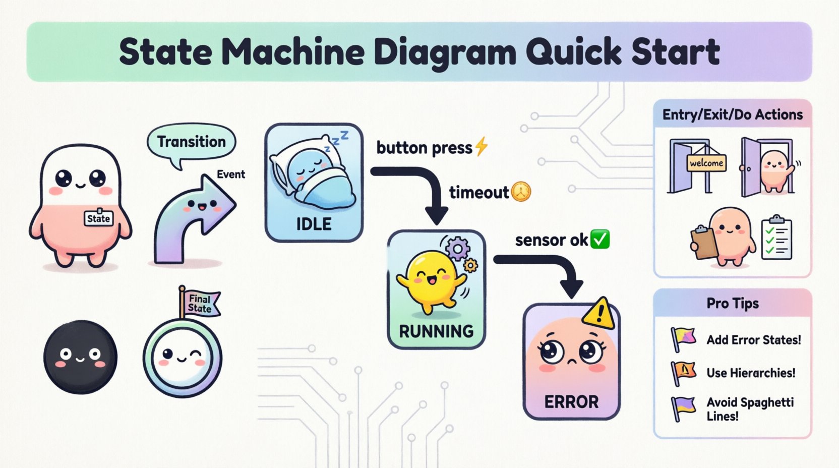
📊 Understanding the Core Components
Every state machine consists of a few fundamental building blocks. Understanding these elements is critical for accurate modeling. Unlike flowcharts, which focus on the flow of control, state diagrams focus on the status of the system at any given moment. The system resides in a specific condition, waits for an occurrence, and then moves to a new condition.
The following table outlines the essential symbols and their meanings in standard Unified Modeling Language (UML) notation:
| Element | Description | Visual Representation |
|---|---|---|
| State | A condition during which the system satisfies some condition, performs some activity, or waits for an event. | Rounded rectangle with label |
| Transition | The movement from one state to another triggered by an event. | Arrow with label |
| Event | A signal or action that triggers a transition. | Text on the transition arrow |
| Action | Activity performed when entering, exiting, or within a state. | Text inside the state box or on transition |
| Initial State | The starting point of the machine. | Filled black circle |
| Final State | The termination point of the machine. | Double-bordered circle |
By keeping these definitions clear, you ensure that anyone reviewing the diagram understands the intended behavior. Ambiguity in state definitions often leads to bugs in the final implementation.
🔄 Defining States and Transitions
Constructing the diagram begins with identifying the distinct states the system must occupy. These are not just program variables; they represent the operational mode of the hardware or software. A well-defined state machine minimizes the number of states required while covering all necessary scenarios.
Consider the following principles when defining states:
- Exhaustiveness: Every possible condition must be accounted for. If the system is not in State A, it must be in State B or C.
- Exclusivity: The system should typically be in only one state at a time (unless using orthogonal regions).
- Stability: A state implies that the system is stable in that condition, waiting for a trigger to change.
Transitions are the bridges between these states. They are triggered by events. An event can be internal (a timer expiring) or external (a button press, a sensor reading).
When drawing transitions, ensure the direction is clear. The arrow points from the source state to the target state. The label on the arrow describes the event causing the move. If multiple events can trigger the same transition, you may list them separated by commas, though keeping them distinct often aids readability.
⚙️ Actions and Events: The Lifeblood of Logic
Events drive the state machine, but actions define what happens during the change. In embedded systems, actions often map directly to hardware registers or API calls. It is crucial to distinguish between events and actions.
Entry, Exit, and Do Actions
Complex states often require logic to run at different points in time. UML allows you to specify three types of actions within a state:
- Entry Action: Executed immediately when the state is entered. Use this to initialize hardware, set flags, or reset timers.
- Exit Action: Executed immediately before leaving the state. Use this to clean up resources, save data, or deactivate outputs.
- Do Action: Continues to execute while the system remains in the state. This is often used for polling sensors or monitoring conditions without waiting for a specific event.
For example, in a “Motor Running” state, the Entry action might enable the power driver. The Do action might continuously read the current sensor. The Exit action might ramp down the power to prevent spikes.
🏗️ Advanced Notation Techniques
As systems grow, simple linear state diagrams become difficult to manage. Advanced notation helps organize complexity without creating visual spaghetti. These features allow you to nest logic and manage history.
Hierarchical States
Not all states are equal. Some states are composite, containing sub-states. This is known as a composite state. Inside a composite state, you can define specific sub-behaviors. This is vital for embedded logic where a high-level mode (like “Idle”) might have several low-level variations (like “Waiting for Sensor”, “Waiting for Timer”, “Waiting for User Input”).
Using hierarchy reduces the number of transitions. Instead of drawing a line from every sub-state to every other sub-state, you can define transitions at the parent level. This keeps the diagram clean and manageable.
History States
Sometimes, when a system leaves a composite state and returns later, it should not restart from the beginning. It should remember where it left off. This is the function of the History State.
- Deep History: The system remembers the specific sub-state it was in previously.
- Shallow History: The system remembers the composite state itself but enters a default sub-state within it.
This is particularly useful for power management systems. If a device enters a low-power mode and wakes up, it should resume exactly where it was in the task queue, not restart the entire sequence.
📝 Designing the Logic Flow
Creating a diagram from scratch can be daunting. A structured approach ensures that no logic gaps are missed. Follow this workflow to move from a blank page to a validated design.
- Gather Requirements: List all inputs, outputs, and expected behaviors. What triggers a change? What must happen in response?
- Identify States: Define the distinct modes of operation. Ask: “What does the system look like when it is doing this specific thing?”
- Define Events: List all signals that can cause a move. Include error signals and timeouts.
- Map Transitions: Draw the arrows. Ensure every state has a path out, except for the final state. Ensure every state has a path in, except for the initial state.
- Assign Actions: Add the entry, exit, and do actions to the relevant states.
- Review Guards: Check if any transitions require a condition (guard) to proceed. A guard is a boolean expression that must be true for the transition to fire.
🛠️ Mapping Logic to Code
Once the diagram is complete, the translation to code becomes a structured exercise. The diagram acts as the specification. There are several common patterns for implementation.
Switch-Case Implementation
The most direct mapping uses a state variable and a switch statement. Each state corresponds to a case label. Inside the case, you handle the logic for that state and the transition checks.
- State Variable: An integer or enum representing the current state.
- Event Handler: A function that receives the event and updates the state variable based on the current state.
- Actions: Call functions within the state machine loop that correspond to the entry/exit/do actions defined in the diagram.
State Table Implementation
For more complex systems, a lookup table can define transitions. Each row contains the current state, the event, the next state, and the action to perform. This decouples the logic from the control flow, making it easier to modify behavior without changing code structure.
| Current State | Event | Next State | Action |
|---|---|---|---|
| IDLE | START_BUTTON | RUNNING | Initialize Motor |
| RUNNING | STOP_BUTTON | IDLE | Disable Motor |
| RUNNING | OVERRIDE | ERROR | Log Fault |
This approach is highly maintainable. If a requirement changes, you update the table row rather than rewriting conditional logic.
⚠️ Common Pitfalls and Solutions
Even experienced designers encounter issues. Being aware of common traps helps you avoid them early.
- Missing Error States: Designers often focus on the happy path. If a sensor fails, where does the state machine go? Always define an ERROR or SAFE state that handles faults.
- Unreachable States: Ensure every state is reachable from the initial state. Dead states indicate a design flaw.
- Too Many States: If you have more than 15 states, review your hierarchy. You may be flattening nested states that should be grouped.
- Missing Guards: If a transition depends on a condition, explicitly mark it with a guard. Do not rely on the event alone if the context matters.
- Spaghetti Transitions: Avoid crossing lines. If the diagram becomes unreadable, use composite states to group related logic.
🔍 Debugging State Flows
When the embedded system behaves unexpectedly, the state machine diagram is your first place to look. Debugging involves tracing the path taken by the system.
Use logging to record state changes. When an error occurs, check the log to see:
- Which state was active?
- What event triggered the change?
- Was the transition guard satisfied?
- Did the action execute correctly?
Visualizing the actual execution path against the diagram often reveals where the logic diverged. If the code follows a path not shown on the diagram, the implementation does not match the design.
📈 Scaling for Complex Systems
For large-scale embedded applications, a single diagram may not suffice. You may need to decompose the system into multiple interacting state machines. This is known as concurrent or orthogonal state design.
In this pattern, different parts of the system operate independently but synchronize via events. For instance, a communication module might have its own state machine independent of the motor control machine. They interact only when necessary.
- Separation of Concerns: Keep the user interface logic separate from the hardware control logic.
- Event Broadcasting: Use a global event bus for communication between machines, ensuring loose coupling.
- Shared Variables: Be cautious with shared data. Ensure thread safety if multiple machines access the same resource.
This architecture improves testability. You can test the motor machine in isolation from the communication machine.
✅ Finalizing Your Design
Before moving to implementation, review the diagram against the original requirements. Does it cover every scenario? Is the logic deterministic? Can a developer understand it without asking questions?
A well-crafted state machine diagram is a communication tool as much as a technical document. It aligns the team on how the system behaves. It reduces the cognitive load during debugging. It serves as a reference for future maintenance.
By following these guidelines, you establish a solid foundation for reliable embedded logic. The transition from a blank page to a working system becomes a structured journey rather than a guesswork process. Focus on clarity, completeness, and precision, and the resulting code will reflect that discipline.
Start with the basics. Define your states clearly. Map your transitions accurately. Handle your errors gracefully. With practice, designing state machines becomes a natural part of your development workflow, ensuring your embedded systems perform reliably in the real world. 🛠️
