


Designing reliable control systems for robotics requires precision. A single logic error in firmware can halt operations or cause hardware damage. State machines provide a structured approach to managing complex behaviors. When implemented correctly, they enhance predictability and maintainability. However, improper design introduces risks like deadlocks. These conditions freeze the system, preventing further progress.
This guide explores best practices for UML state machine diagrams. The focus is on robotics firmware contexts. We examine how to structure transitions, manage resources, and handle concurrency. The goal is robustness without unnecessary complexity.
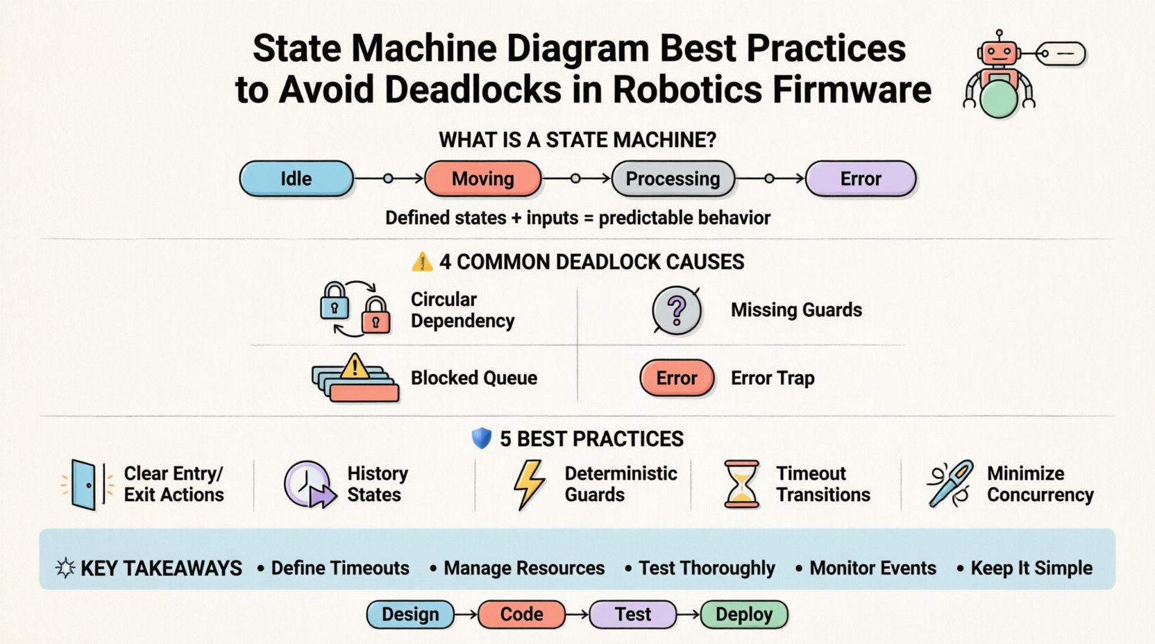
🧠 Understanding State Machines in Robotics
A state machine is a mathematical model of computation. It describes a system that moves between defined states based on inputs. In robotics, these inputs often come from sensors, user commands, or internal timers. The states represent specific operational modes, such as “Idle”, “Moving”, “Processing”, or “Error”.
Why use state machines?
- Clarity: Visual diagrams map logic flow clearly.
- Completeness: Ensures all scenarios are accounted for.
- Maintainability: Changes are localized to specific states or transitions.
- Debugging: Easier to trace execution paths during failures.
However, embedded systems have constraints. Memory is limited. Processing power is finite. Timing is critical. A deadlock occurs when two or more states wait indefinitely for each other. This often happens due to circular dependencies or resource contention.
⚠️ Common Causes of Deadlocks in Firmware
Before applying fixes, one must understand the root causes. Deadlocks in robotics firmware usually stem from how events are queued and how resources are acquired.
1. Circular Resource Dependency
State A waits for a resource held by State B. State B waits for a resource held by State A. Neither can proceed. This is classic in multi-threaded or multi-process architectures.
2. Missing Transition Guards
If a transition condition is never met, the system remains in a state forever. This looks like a deadlock to the operator, though technically it is a logical stall.
3. Blocking Event Queues
High-priority events get stuck behind low-priority ones. If the queue fills up, new events are dropped or the system blocks waiting for space.
4. Improper Error Handling
When an error occurs, the machine transitions to an “Error” state. If that state has no defined exit condition, the robot stops responding to all inputs.
🛡️ Best Practices for Diagram Design
Designing the diagram is the first line of defense. The visual model must be translated into code without introducing logic errors.
1. Define Clear Entry and Exit Actions
Every state should have defined behaviors upon entry and exit. This ensures resources are managed consistently.
- Entry Actions: Initialize variables, start timers, or enable sensors.
- Exit Actions: Stop actuators, release locks, or log data.
- Effect: Actions taken immediately upon a transition.
Example:
- Entering Motion state: Enable motor driver.
- Exiting Motion state: Disable motor driver.
2. Use History States for Complex Submachines
Complex robots have nested behaviors. Orthogonal regions allow independent processes to run simultaneously. History states remember the last active sub-state.
- Deep History: Returns to the deepest active state.
- Shallow History: Returns to the most recently entered state at that level.
This prevents the system from resetting to a default state every time a sub-machine is re-entered, reducing latency and potential race conditions.
3. Guard Conditions Must Be Deterministic
Guards decide if a transition occurs. They must evaluate quickly and consistently. Avoid complex calculations inside guard conditions.
- Bad: Checking a long list of sensor values with nested loops.
- Good: Checking a boolean flag set by a background task.
4. Implement Timeout Transitions
No state should wait indefinitely for an event. A timeout ensures progress.
- Set a maximum duration for a state.
- Define a transition on timeout to an error or idle state.
- This prevents hanging on network latency or sensor delays.
5. Minimize Concurrent Regions
Concurrent regions (orthogonal states) are powerful but risky. More regions mean more potential for synchronization errors.
- Keep regions independent where possible.
- Use event broadcasting carefully.
- Avoid shared mutable state between concurrent regions.
🔄 Handling Transitions and Events
The movement between states is where most logic errors occur. Event processing order matters significantly.
Event Prioritization
Not all events are equal. A hardware failure event must override a status update event. Define priority levels in the diagram.
Transition Triggers
Ensure every state has a defined response to every relevant event. If an event is ignored, it is treated as a no-op. If an event is unexpected, it might trigger an undefined behavior.
Self-Transitions
Using a self-transition (staying in the same state) can be useful for handling retries or loops. However, avoid infinite loops within a self-transition without a break condition.
📊 Comparison of Transition Strategies
| Strategy | Pros | Cons | Deadlock Risk |
|---|---|---|---|
| Immediate Execution | Faster response time | Harder to interrupt | Low |
| Deferred Execution | Allows preemption | Higher latency | Medium |
| Event Queueing | Handles bursts | Memory overhead | High (if queue blocks) |
| Interrupt Driven | Real-time responsiveness | Complex synchronization | Medium |
🧩 Managing Resources and Locks
Firmware often interacts with hardware peripherals. These resources need exclusive access to prevent corruption.
Resource Allocation
Apply strict rules for acquiring locks.
- Acquire locks in a consistent order across all states.
- Release locks immediately after use.
- Never hold a lock while waiting for another resource.
Deadlock Prevention Matrix
Use a matrix to track resource dependencies.
- List all states.
- List all resources.
- Mark which states hold which resources.
- Identify cycles in the dependency graph.
If a cycle exists, redesign the state flow to break it.
🧪 Testing and Validation
Designing the diagram is only half the work. Verification ensures the implementation matches the model.
Model-in-the-Loop Testing
Run the state machine logic in a simulation environment before deploying to hardware. This allows for stress testing without risking physical components.
Hardware-in-the-Loop Testing
Connect the firmware to a simulated physical environment. Verify timing constraints and sensor feedback loops.
Fuzz Testing
Inject random events into the system. Observe if the state machine handles unexpected inputs gracefully or crashes.
Logging and Tracing
Implement detailed logging for state transitions.
- Log entry and exit timestamps.
- Log event triggers and transition outcomes.
- Log resource acquisition and release.
This data is vital for diagnosing intermittent deadlocks that occur only under specific conditions.
🔍 Analyzing Specific Deadlock Scenarios
Let us look at concrete examples of where things go wrong in robotics firmware.
Scenario 1: The Sensor Wait
State: Waiting for Lidar Data.
Condition: Transition only on “DataReceived”.
Problem: If the sensor fails to send data, the state never exits. The robot freezes.
Solution: Add a timeout transition. If “DataReceived” does not arrive within 5 seconds, transition to “SensorError” state.
Scenario 2: The Motor Lock
State: Charging Battery.
Condition: Transition to “Idle” when BatteryFull.
Problem: The “BatteryFull” event is generated by a charging circuit. The main processor never polls the status register.
Solution: Ensure the interrupt handler posts the event to the state machine queue. Do not rely on polling in a busy loop.
Scenario 3: The Nested Call
State: Navigation.
Condition: Calls sub-function “PathPlanning”.
Problem: “PathPlanning” blocks for 10 seconds. The state machine cannot process other events during this time.
Solution: Offload long tasks to a background thread. Post a “PlanningComplete” event to the main state machine.
🔧 Coding Implementation Patterns
The diagram must map cleanly to code. Several patterns exist to achieve this.
Switch-Case Pattern
Use a main loop that switches on the current state variable. This is simple but can become unwieldy with many states.
- Pros: Easy to read for simple machines.
- Cons: Hard to refactor, prone to typos in case labels.
State Object Pattern
Each state is a class implementing a common interface. The main loop calls the current state’s handle method.
- Pros: Encapsulates logic, easier to extend.
- Cons: More overhead, more memory usage.
Table-Driven Approach
Store transitions in a data table. The engine looks up the next state based on current state and event.
- Pros: Highly configurable, separates data from logic.
- Cons: Debugging can be harder, requires a robust engine.
🛠️ Optimization for Embedded Constraints
Robotics firmware often runs on microcontrollers with limited RAM and CPU.
Memory Management
- Avoid dynamic allocation for state objects during runtime.
- Pre-allocate event buffers at startup.
- Use fixed-size buffers for strings and logs.
CPU Utilization
- Keep state transitions atomic.
- Minimize the time spent inside a transition handler.
- Use interrupts only for hardware events, not software logic.
📈 Maintenance and Evolution
Robots evolve. Requirements change. The state machine must adapt.
Version Control
Keep state diagrams in version control alongside source code. This ensures the model matches the implementation.
Documentation
Annotate the diagram with comments explaining complex logic. Do not rely on the diagram alone.
Refactoring
When adding new features, review existing states. Ensure new logic does not introduce new deadlock paths.
🚀 Summary of Key Takeaways
Building reliable robotics firmware requires disciplined design. State machines are a powerful tool, but they demand careful management of events and resources.
- Define Timeouts: Never let a state wait forever.
- Manage Resources: Avoid circular dependencies.
- Test Thoroughly: Use simulation and fuzzing.
- Monitor Events: Ensure all inputs are processed.
- Keep it Simple: Reduce complexity where possible.
By following these practices, developers can create systems that are resilient and predictable. The focus remains on functionality and safety. Avoiding deadlocks ensures the robot completes its mission without interruption.
🔮 Future Considerations
As robotics systems become more autonomous, state machines will need to integrate with higher-level decision-making layers. Machine learning models may suggest actions, but the state machine should remain the guard rail.
- Ensure interfaces between AI and state logic are well-defined.
- Allow for graceful degradation if the AI layer fails.
- Continue to prioritize deterministic behavior over probabilistic outcomes in critical paths.
The foundation of any robust system is a clear understanding of its operational states. Invest time in the design phase. A well-structured diagram pays dividends in the field.
📝 Final Notes on Implementation
Remember that the diagram is a contract. It defines how the system behaves under all conditions. Treat it as such. Review it with peers. Challenge the assumptions. Test the edge cases. This diligence is what separates functional prototypes from production-ready firmware.
When a deadlock occurs, do not assume it is a hardware fault. It is often a logic flaw. Revisit the state transitions. Check the guards. Verify the event flow. The solution lies in the design.
Adopting these best practices leads to systems that are easier to debug, safer to operate, and more efficient to maintain. The path to reliability is paved with clear states and defined transitions.
