


Internet of Things (IoT) development involves more than just connecting sensors to the cloud. It requires robust logic to handle device behavior, ensure reliability, and manage resources effectively. For developers entering this space, understanding how to model system behavior is critical. One of the most powerful tools available for this purpose is the State Machine Diagram within the Unified Modeling Language (UML) ecosystem. This guide explores the fundamentals of state machines, their specific application in IoT firmware, and how to design reliable logic without relying on complex software products.
Understanding the Core Concept 🔌
A state machine is a mathematical model of computation used to design computer programs and digital logic circuits. In the context of embedded systems and IoT, it provides a structured way to define how a device behaves under different conditions. Unlike a linear script that executes from top to bottom, a state machine waits for specific events to trigger changes in its internal status.
Imagine a smart door lock. It does not simply run code once and stop. It waits for a button press, checks a battery level, verifies a PIN code, and then decides whether to unlock or lock. Each of these moments represents a state. The movement from one condition to another is a transition. Visualizing this flow helps prevent bugs where a device might try to connect to the network while in a low-power sleep mode.
Key Components of a State Machine Diagram 📊
To build an accurate representation of your IoT device, you must understand the building blocks. Every diagram relies on these fundamental elements:
- States: These represent a condition during the life of an object or system. For a sensor, a state could be Idle, Sensing, Transmitting, or Error.
- Transitions: The arrow connecting two states. This indicates the movement from one condition to another.
- Events: The trigger that causes a transition. Examples include Button Pressed, Network Timeout, or Battery Critical.
- Guard Conditions: Boolean expressions that must evaluate to true for a transition to occur. For example, a transition to Connect might only happen if BatteryLevel > 20%.
- Actions: Activities performed when entering, exiting, or while inside a state. This includes logging data, turning on LEDs, or resetting timers.
Why IoT Devices Need State Management ⚙️
IoT hardware operates under strict constraints. Unlike a server with infinite resources, an IoT node often runs on limited battery power and has constrained processing capabilities. A flat, procedural approach to coding often leads to race conditions and unpredictable behavior. State machines offer several distinct advantages in this environment.
1. Predictability and Reliability
When every possible state is defined, you know exactly how the system will react to an input. If the device is in the Offline state and receives a Connect event, the behavior is deterministic. This predictability is vital for safety-critical applications, such as industrial monitoring or medical devices.
2. Resource Optimization
State machines allow you to disable features that are not currently needed. If the device is in Deep Sleep, the radio module and high-precision sensors are powered down. Only a low-power interrupt remains active. This drastically extends battery life.
3. Handling Concurrency
Real-world devices often do multiple things at once. A smart thermostat might be monitoring temperature while waiting for a user command. Advanced state modeling allows for hierarchical and orthogonal states, enabling parallel processing logic without complex threading.
4. Error Recovery
Hardware failures are inevitable. A state machine can include specific Error states designed to reset peripherals, attempt reconnection, or enter a safe mode. Without this structure, an error might freeze the entire application.
Designing for Constraints: The Table Approach 📋
Before drawing diagrams, it is helpful to map out the logic in a table format. This ensures clarity regarding events, conditions, and actions.
| Current State | Event | Guard Condition | Target State | Action |
|---|---|---|---|---|
| Idle | Button Press | Battery > 10% | Active | Start Timer |
| Active | Timer Expiry | None | Idle | Power Down Radio |
| Active | Network Error | Retry Count < 3 | Retry | Increment Retry Counter |
| Retry | Network Success | None | Active | Reset Retry Counter |
This tabular view simplifies the translation of logic into code. It forces the developer to consider edge cases, such as what happens if the battery dies during the Active state.
Advanced Concepts: Hierarchical and Orthogonal States 🔄
Simple state machines work for basic devices, but complex IoT systems require more advanced modeling techniques. These techniques help manage complexity without creating spaghetti diagrams.
1. Hierarchical State Machines
Also known as nested states, this allows you to define a state that contains sub-states. For example, consider a Connectivity state. Inside this state, you might have sub-states for Connecting, Connected, and Disconnected. If the parent Connectivity state is entered, the system defaults to Connecting. If the device switches to Idle, the entire Connectivity hierarchy is exited. This reduces redundancy in your logic.
2. Orthogonal Regions
Orthogonal states represent independent aspects of the system running simultaneously. Think of a smart watch. One region might manage the Timekeeping state (second hand movement, hour display), while another manages the Sensor state (heart rate monitoring). These regions operate in parallel. A transition in one region does not block the other.
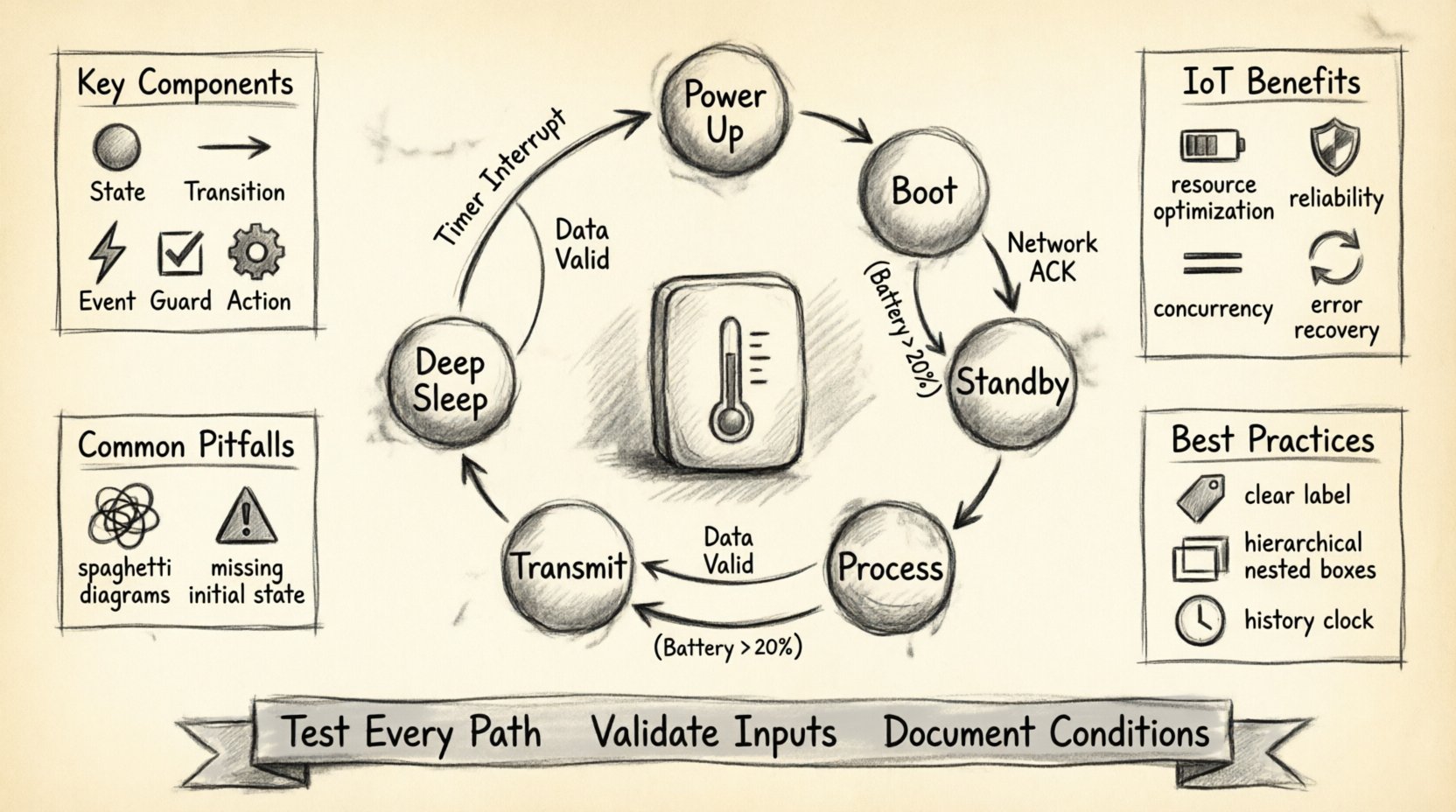
Practical Example: A Smart Temperature Sensor 🌡️
Let us walk through a concrete scenario. You are building a sensor that sends temperature data to a server. The device must manage battery, network connectivity, and measurement cycles.
State Breakdown
- Power Up: The initial state. Hardware initializes. The system checks voltage levels.
- Boot: Firmware loads. The system verifies the integrity of the storage.
- Standby: The device waits for a wake-up signal. Power consumption is minimal.
- Measure: The sensor reads the temperature. The ADC (Analog-to-Digital Converter) is active.
- Process: Data is filtered or calibrated. Logic runs locally.
- Transmit: The radio module connects to the gateway and sends the packet.
- Retransmit: If the gateway acknowledgment fails, the device waits and tries again.
- Deep Sleep: If battery is low, the device enters a low-power state for extended periods.
Transition Logic
Consider the transition from Standby to Measure. This event is triggered by a timer interrupt. Once the Measure state is entered, an action records the timestamp. Upon completion, the system transitions to Process. If the data is valid, it goes to Transmit. If the data is invalid, it loops back to Standby to save the corrupted reading.
Common Implementation Pitfalls ⚠️
Even experienced engineers make mistakes when modeling state logic. Being aware of these common issues can save significant debugging time.
- Missing Initial State: Every diagram needs a clear entry point. Without a defined start state, the system behavior upon power-up is undefined.
- Unreachable States: If a state has no incoming transitions, it will never be reached. This indicates a logic gap or dead code.
- Spaghetti Diagrams: Avoid excessive crossing lines. If a diagram becomes too complex, it fails its purpose. Use hierarchical states to simplify.
- Ignoring Entry/Exit Actions: Developers often forget to run cleanup code when leaving a state. For example, closing a file handle or turning off an LED.
- Event Storming: Too many events triggering transitions can make the machine hard to maintain. Consolidate events where possible.
- Blocking Transitions: Ensure transitions do not wait indefinitely. If a network request hangs, the state machine should freeze. Use timeouts and watchdog timers.
Best Practices for Embedded Design 🛠️
Adhering to specific guidelines ensures your state machine remains maintainable and scalable.
1. Keep States Granular but Manageable
Do not make every function a state, and do not make one giant state for everything. A good rule of thumb is that a state should represent a distinct mode of operation. If a state contains too much logic, split it into sub-states.
2. Use Clear Naming Conventions
Name states and events descriptively. Instead of S1 or Event1, use LowPowerMode or ButtonPressed. This makes the diagram readable for other team members.
3. Implement History States
History pseudostates allow the system to remember the last active sub-state. If a device is in Connected inside the Online state, and it briefly goes to Offline, it can return to Connected rather than re-initializing. This saves processing time and power.
4. Validate Input Events
Never assume an event will arrive cleanly. Validate signals before processing. If a sensor provides noisy data, the state machine should have a mechanism to filter or ignore it before triggering a transition.
5. Document Guard Conditions Explicitly
When a transition has a condition, document the expected values. For example, Guard: Voltage > 3.0V. This prevents future confusion about why a transition did not occur.
Testing State Machines 🧪
Once the design is complete, testing is crucial. You cannot simply run the code and hope it works. You need a strategy to verify every path.
1. Path Coverage
Ensure every transition line in your diagram has been tested. If you have 50 transitions, you need test cases that trigger each one.
2. Stress Testing
Send events rapidly to see if the machine handles race conditions. Can it handle a Button Press and a Network Timeout simultaneously?
3. Recovery Testing
Simulate power failures mid-transition. Does the device boot up in a known good state? Does it recover data integrity?
4. Static Analysis
Use tools to check for unreachable code or undefined states. Many development environments can analyze state logic to catch syntax errors in the flow.
Integration with the Development Workflow 🔄
State machine diagrams should not be created in isolation. They are part of the broader software development lifecycle.
- Requirement Phase: Use the diagram to clarify requirements with stakeholders. Does the device handle power loss correctly?
- Design Phase: Translate the diagram into code structures. Many languages have libraries or patterns for implementing state machines.
- Implementation Phase: Write the code corresponding to the states. Use switch statements or class inheritance depending on the language.
- Review Phase: Peer review the diagram against the code. Ensure the implementation matches the design.
Conclusion on Logic and Reliability ✅
Building IoT solutions requires a solid foundation in system design. State machine diagrams provide a visual and logical framework to manage the complexity of connected devices. By defining states, transitions, and events clearly, developers can create firmware that is robust, efficient, and easy to debug.
As you progress in your career, you will encounter more complex scenarios involving cloud synchronization, over-the-air updates, and multi-device coordination. The principles of state modeling remain constant. A well-designed state machine reduces the cognitive load on the developer and increases the trustworthiness of the hardware.
Focus on clarity, test thoroughly, and always consider the physical constraints of the device. With these practices, you can build systems that perform reliably in the real world.
