


Internet of Things (IoT) devices operate in environments where predictability is often low, and resources are strictly limited. Unlike general-purpose computing, embedded systems must handle events asynchronously while managing power consumption and connectivity reliability. A State Machine Diagram provides the structural clarity needed to manage this complexity. Within the Unified Modeling Language (UML) framework, this diagram type maps the lifecycle of an object or system through various conditions.
For developers working on firmware, gateways, or cloud-connected sensors, understanding Finite State Machines (FSM) is not optional—it is critical. This guide explores the anatomy of state machines, their specific application in IoT architecture, and how to translate visual models into robust code without relying on external tools or hype.
Understanding the Core Concept 🧠
A State Machine Diagram models the behavior of a single object or system. It defines the different states the object can exist in and the transitions between those states based on specific events. Think of it as a flowchart that remembers where it has been. In IoT, this memory is vital for maintaining context during network interruptions or power cycles.
Consider a smart thermostat. It is not simply “on” or “off.” It might be heating, cooling, idle, waiting for sensor data, or in calibration mode. Without a state machine, logic for switching between these modes can become tangled spaghetti code. The diagram imposes order.
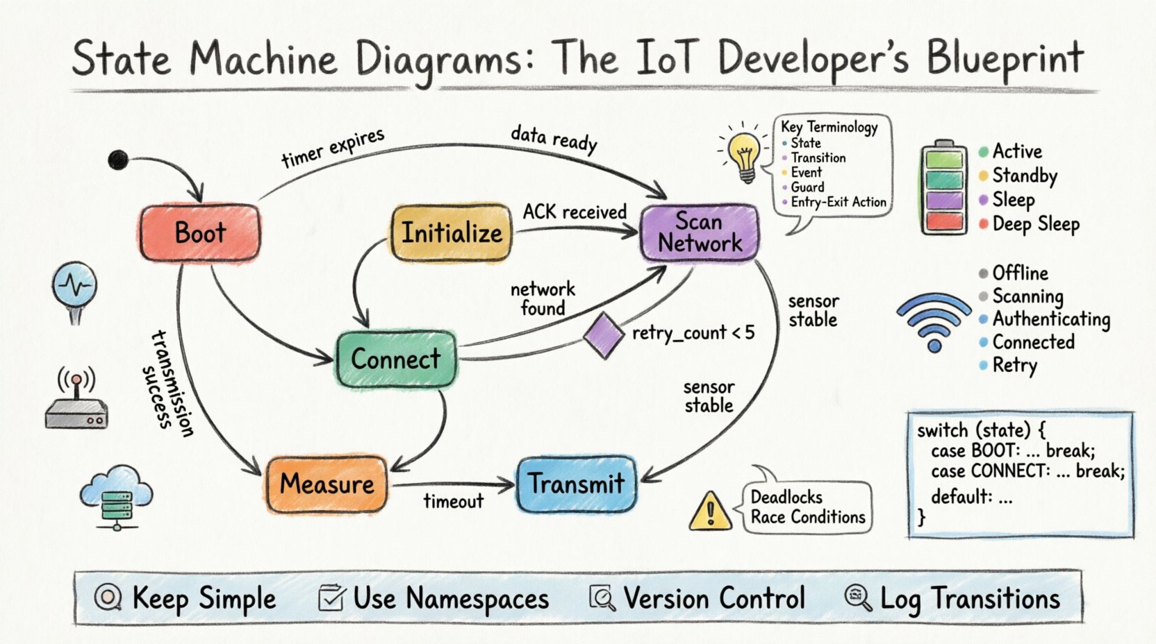
Key Terminology
- State: A condition during which the system performs a specific task or waits for input. Represented as a rounded rectangle.
- Transition: The movement from one state to another. Represented as an arrow.
- Event: The trigger that initiates a transition (e.g., a button press, a timer expiration, or a network packet arrival).
- Guard Condition: A boolean expression that must be true for a transition to occur. It acts as a filter.
- Entry/Exit Action: Code or logic executed when entering or leaving a specific state.
Why IoT Systems Demand State Machines ⚙️
IoT devices face unique challenges that traditional web applications do not. The constraints of embedded hardware necessitate a disciplined approach to logic management. Here is why a State Machine Diagram is foundational:
- Resource Management: Devices often run on batteries. A state machine explicitly defines Sleep and Active modes, ensuring power is only consumed when necessary.
- Event-Driven Architecture: IoT is reactive. A device waits for data. A state machine handles waiting efficiently without blocking the processor.
- Error Recovery: Networks fail. Sensors drift. A state machine can define an Error state that triggers a reset or a fallback mechanism, preventing the device from hanging in an undefined state.
- Concurrency Handling: Complex systems need to run multiple processes. State machines help visualize how these processes interact or synchronize.
Anatomy of the Diagram 🔍
To build a reliable system, you must understand the building blocks. Below is a breakdown of the components you will encounter when designing these models.
| Component | Visual Representation | Function in IoT Context |
|---|---|---|
| Initial State | Filled Circle (●) | Where the system starts upon power-up or reset. |
| Final State | Filled Circle with Border (⊙) | Indicates a terminal state (rare in IoT, as devices usually loop). |
| State | Rounded Rectangle | Represents a stable condition (e.g., Connected, Scanning). |
| Transition | Arrow with Label | Shows the path taken when an event occurs. |
| History State | Circle with ‘H’ | Remembers the last active state before entering a composite state. |
Designing for Connectivity and Power 🔋
In IoT development, two factors dominate design: connection reliability and power consumption. A well-crafted state machine addresses both simultaneously. We can categorize states into logical groups to simplify the diagram.
1. Power Management States
Battery life is often the primary metric for IoT success. The state machine must explicitly handle power transitions.
- Active: Processor is running at full speed. Sensors are reading. Radio is transmitting.
- Standby: Processor is running at low speed. Sensors are off. Radio is listening for wake-up signals.
- Sleep: Processor is halted. Only a timer or interrupt can wake the system. Power draw is minimal.
- Deep Sleep: Most peripherals are powered down. Waking up requires a significant reset sequence.
Transitions between these states often depend on timers or external triggers. For example, if no data is transmitted for 5 minutes, the system transitions from Active to Standby. If no activity occurs for 1 hour, it moves to Sleep.
2. Network Connectivity States
IoT devices often struggle with unstable connections. The logic must handle retries without entering a loop.
- Offline: No network interface is available.
- Scanning: Searching for available networks or gateways.
- Authenticating: Handshaking with the server or gateway.
- Connected: Secure tunnel established. Data exchange possible.
- Retry: Temporary state after a failed attempt.
A common pitfall is the Retry state. If a device retries indefinitely without a backoff strategy, it drains the battery and clogs the network. The state machine should enforce a Guard Condition on the retry transition. For instance: retry_count < 5. If this fails, the system transitions to a Wait state instead of looping.
Common Design Patterns in Embedded Systems 🛠️
While every device is unique, several patterns recur frequently in IoT firmware. Recognizing these patterns helps in creating standard diagrams.
The Ping-Pong Pattern
Used for request-response protocols. The device sends a command and waits for a specific acknowledgment before moving to the next state.
- State A: Send Request.
- Transition: Wait for ACK.
- State B: Process Response.
- Transition: If NACK, go to State A (Retry) or State C (Error).
The Watchdog Pattern
Ensures the system does not hang. A timer triggers a transition to a reset state if the main loop does not report progress within a set time.
- State: Running.
- Event: Timeout.
- Transition: Reset System.
The Hierarchical State Pattern
For complex devices, flat diagrams become unreadable. Hierarchical states allow you to nest states. For example, a Network super-state could contain Wifi, Bluetooth, and Cellular sub-states. This reduces visual clutter and groups related logic.
Mapping Diagrams to Code 📝
Once the diagram is finalized, the translation to source code must be precise. The goal is to keep the logic close to the visual model. This makes debugging easier because you can look at the diagram to understand the code flow.
Switch-Case vs. Object-Oriented
Many developers use a large switch statement based on an integer state variable. While functional, this can become hard to maintain as the number of states grows.
A more scalable approach involves a state object pattern. Each state is a class or struct with methods for onEntry, onExit, and handleEvent. The main loop calls the current state’s handler.
- Entry Actions: Initialize GPIO pins, start timers, log the state change.
- Exit Actions: Stop timers, clear buffers, save configuration to flash.
- Internal Actions: Logic that runs while remaining in the same state (e.g., checking sensor values).
Logging State Changes
In production, you cannot always attach a debugger. Logging state transitions is a best practice. Every time a transition occurs, the system should write a log entry.
LOG("Transition: Active -> Sleep")
This allows you to trace the lifecycle of the device remotely. If a device stops reporting, the last log entry tells you exactly which state it was in when it went silent.
Debugging and Troubleshooting 🔧
Even with a perfect diagram, implementation errors occur. Common issues in IoT state machines include race conditions, deadlocks, and unintended state jumps.
1. Deadlocks
A deadlock occurs when the system enters a state with no outgoing transitions. This often happens if a specific event is never triggered. To prevent this, ensure every state has a defined exit path, even if it is a self-loop or a transition to a default Reset state.
2. Race Conditions
Interrupts can occur while the main loop is processing a state transition. If an interrupt changes a variable that the state machine relies on, the logic might break. Use atomic operations or critical sections when updating state variables.
3. Invalid Transitions
What happens if an event occurs that is not defined for the current state? The diagram should account for this. A common strategy is a Global State or AnyState handler that catches unexpected events and logs them for analysis.
Real-World Scenario: Smart Sensor Node 📡
Let us apply this to a practical example. Imagine a temperature sensor node that sends data to a cloud platform every 10 minutes.
State Flow
- Boot: Initialize hardware, load config from non-volatile memory.
- Initialize Radio: Check if the radio module is ready.
- Scan Network: Look for the gateway.
- Connect: Establish handshake.
- Measure: Read the sensor.
- Transmit: Send data packet.
- Acknowledge: Wait for cloud confirmation.
- Sleep: Enter low-power mode for 10 minutes.
If the connection fails at the Connect step, the guard condition checks the retry count. If retries are exhausted, it moves to a Wait state for 1 hour before trying again. This prevents battery drain from constant reconnection attempts.
Best Practices for Documentation 📚
A state machine diagram is a living document. As the product evolves, the diagram must evolve with it. Adhere to these practices to maintain clarity.
- Keep it Simple: If a diagram has too many states, consider splitting the system into multiple interacting state machines.
- Use Namespaces: Prefix state names with the component name to avoid confusion (e.g.,
WiFi.Connecting,WiFi.Connected). - Version Control: Store the diagram in the same repository as the code. Changes to logic should include updates to the diagram.
- Review Regularly: During code reviews, check if the implementation matches the diagram. If they diverge, update the diagram immediately.
Advanced Considerations: Hierarchical States 📉
When systems grow, flat state diagrams become difficult to read. Hierarchical State Machines (HSM) allow you to define Super States.
For example, a Communication super state might contain Wifi, LoRa, and Bluetooth sub-states. If the device switches from Wifi to LoRa, it can exit the Communication super state and re-enter it with the new mode. This saves space and logic.
History States in HSM
When exiting a super state and re-entering it later, do you return to the initial sub-state or the last active sub-state? A Shallow History node returns to the initial state. A Deep History node remembers the specific sub-state active before the exit. This is crucial for resume functionality after a power cycle.
Final Thoughts on Architecture 🏁
Building IoT systems requires discipline. The unpredictability of the physical world—power fluctuations, signal interference, hardware faults—demands software that is equally resilient. The State Machine Diagram is the blueprint for that resilience.
By defining clear states and transitions, you reduce ambiguity. Developers can read the model to understand the device behavior without reading every line of code. When issues arise, the diagram serves as a map to locate the source of the problem. It turns chaos into order.
Invest time in modeling before writing code. The effort spent on refining the state machine pays dividends during debugging and future maintenance. As you design the next generation of connected devices, let the diagram guide your logic. A well-structured state machine is the backbone of a stable IoT product.
Remember, the goal is reliability. Whether the device is in a factory, a home, or the wild, it must behave as expected. State machines ensure that expectation is met consistently.
