


Embedded systems operate under strict constraints. Memory is finite, timing is critical, and reliability is non-negotiable. In this landscape, defining behavior clearly is paramount. The Unified Modeling Language (UML) State Machine Diagram offers a structured approach to modeling dynamic behavior. Yet, misconceptions persist about its applicability and complexity within resource-constrained environments. This guide separates fact from fiction, providing a technical deep dive into how state machines function in real-world embedded design. We will explore the mechanics, debunk common errors, and outline practical implementation strategies without relying on hype or vague generalizations. 🧐
Understanding the State Machine Diagram in Embedded Context ⚙️
A State Machine Diagram, often referred to as a Statechart Diagram, models the behavior of a system through states, transitions, events, and actions. In embedded engineering, this translates to how a device responds to inputs over time. Unlike a simple flowchart, a state machine remembers its history. This memory is crucial for systems that must maintain context across multiple operations.
Consider a simple traffic light controller. The system does not just change colors; it remembers the current phase and waits for a specific duration before moving to the next. A state machine captures this logic explicitly. It defines:
- States: Conditions or situations during which the system performs an activity or waits for an event. Examples include Idle, Active, Error, or Sleep Mode.
- Transitions: The path taken from one state to another based on a trigger. This includes the guard condition, which determines if the transition is valid.
- Events: Signals that cause a transition. These can be internal (software) or external (hardware interrupts).
- Actions: Activities executed upon entering, exiting, or while staying in a state. Entry actions initialize variables; exit actions clean up resources.
By visualizing these elements, engineers can verify logic before writing a single line of code. This reduces debugging time later in the development cycle. However, several myths surround this methodology.
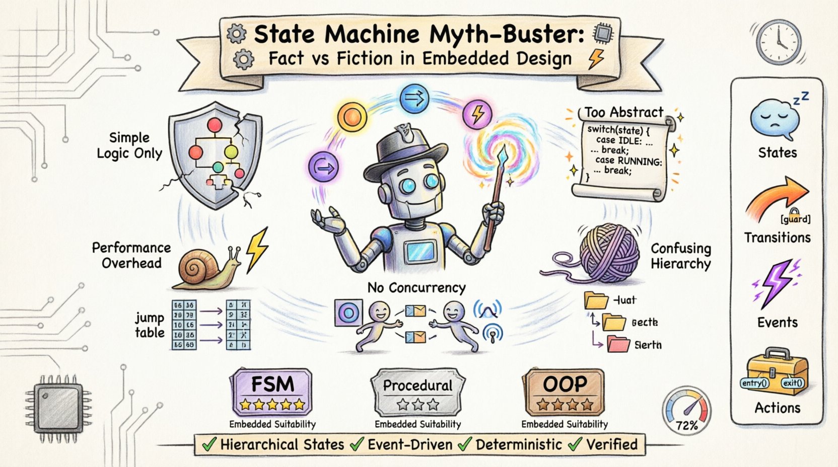
Myth 1: FSMs Are Only for Simple Logic 🚫
A common misconception is that Finite State Machines (FSMs) are too basic for complex embedded applications. Many developers prefer procedural code or object-oriented structures because they feel more flexible. This view overlooks the power of hierarchical state machines.
In modern UML, states can be nested. This allows for Composite States. A composite state contains substates. When the system enters the composite state, it defaults to a specific substate. This structure reduces redundancy. For example, a Communication state can contain substates like Listening, Transmitting, and Retrying.
Complex protocols, such as TCP/IP stacks or Bluetooth handshakes, rely heavily on state logic. The sequence of events is rigid and defined. A state machine enforces this rigidity naturally. It prevents the system from entering an invalid state, such as trying to transmit data before a connection is established.
Fact Check:
- Myth: FSMs handle only simple on/off logic.
- Fact: Hierarchical state machines handle complex protocol stacks and multi-step workflows efficiently.
- Fact: They provide deterministic behavior, which is critical for safety-critical systems.
Myth 2: UML is Too Abstract for Embedded Code 📄
Some engineers argue that UML diagrams are too high-level to translate into efficient machine code. They fear the gap between design and implementation will lead to bloated software. While early tools struggled with this, the relationship between design and code is direct.
A state machine diagram maps directly to a state transition table or a switch-case structure in C or C++. The compiler does not need to interpret the visual diagram; the developer translates the logic. The diagram serves as the specification. If the code matches the diagram, the behavior is predictable.
Implementation Mapping:
| UML Element | Implementation Equivalent | Purpose |
|---|---|---|
| State | Enumeration Value or Struct | Identifies current mode |
| Transition | Conditional Branch (if/else) | Defines logic flow |
| Event | Function Call or Interrupt | Triggers state change |
| Entry Action | Initialization Function | Setup hardware/variables |
| Exit Action | Cleanup Function | Release resources |
This clarity aids in code reviews. When a bug appears, the engineer can trace the path in the diagram. If the diagram says State A goes to State B on Event X, but the code does otherwise, the discrepancy is immediately visible.
Myth 3: Performance Overhead is Unacceptable ⏱️
Embedded systems often run on microcontrollers with limited CPU cycles. There is a persistent fear that state machine logic introduces overhead that cannot be afforded. This belief ignores how state machines are compiled.
Modern compilers optimize state logic very effectively. The resulting machine code is often a series of comparisons and jumps, similar to a switch statement. The overhead is negligible compared to the cost of hardware I/O or sensor polling. In fact, a well-designed state machine can improve performance by reducing polling loops.
Optimization Strategies:
- Jump Tables: Transitions can be implemented via jump tables for O(1) lookup time instead of sequential
if-elsechains. - Minimal State Storage: States can be stored as single integers or bits, consuming minimal RAM.
- Event-Driven Execution: The system processes events only when they occur, avoiding busy-wait loops.
Contrast this with a polling loop that checks every sensor every millisecond regardless of need. A state machine allows the system to sleep until an event wakes it, significantly saving power and CPU cycles.
Myth 4: Hierarchical States Are Confusing 🤯
Designers often avoid hierarchical states because they believe they make the diagram unreadable. They worry about the depth of nesting making logic hard to follow. While excessive nesting is bad practice, appropriate hierarchy improves clarity.
Consider a Power Management state. It contains Normal Operation, Low Power, and Sleep. If these were flat states, you would need to define every transition from every sub-state to external states. This creates a “spaghetti” diagram with hundreds of lines.
With hierarchy, transitions are defined at the composite level. A transition from Low Power to Shutdown applies to all sub-states unless overridden. This reduces diagram clutter and ensures consistency. It is a matter of discipline, not capability.
Myth 5: Concurrency is Impossible in State Machines 🔄
Older state machine definitions struggled with concurrency. In a single thread, only one state exists at a time. Developers assumed this meant embedded systems could not handle multiple processes simultaneously.
UML 2.0 introduced Orthogonal Regions. A single state can contain multiple independent regions. These regions operate concurrently. For example, a device can have one region managing the display and another managing the network connection. Both regions exist within the same composite state but evolve independently.
This feature is vital for modern IoT devices. They must handle user input while simultaneously communicating with the cloud. Orthogonal regions model this parallelism without requiring multiple threads or complex mutex locking in the code structure.
Comparison: FSM vs. Procedural vs. Object-Oriented 📊
To understand where state machines fit, we must compare them to other modeling approaches. Each has strengths and weaknesses depending on the project requirements.
| Approach | Best Use Case | Limitation | Embedded Suitability |
|---|---|---|---|
| State Machine | Discrete event systems, protocol handling, control logic. | Less ideal for continuous data processing. | ⭐⭐⭐⭐⭐ (High) |
| Procedural | Simple scripts, linear algorithms. | Logic becomes hard to maintain as complexity grows. | ⭐⭐⭐ (Medium) |
| Object-Oriented | Complex data relationships, UI applications. | Higher memory footprint, potential runtime overhead. | ⭐⭐⭐⭐ (High) |
The state machine excels where the sequence of events matters more than the data itself. If your system needs to ensure that a motor does not start until a safety door is closed, the state machine enforces this rule strictly. Procedural code might miss this edge case if the condition check is placed in the wrong function.
Implementation Best Practices 🛡️
Designing a robust state machine requires adherence to specific patterns. These practices ensure the code remains maintainable and bug-free.
- One State Per Transition: Avoid multiple transitions entering the same state from different sources unless necessary. Use History States to remember the previous sub-state if returning to a composite state.
- Guard Conditions: Keep guard conditions simple. If the logic inside a guard is complex, move it to a separate function. This keeps the diagram clean.
- Self-Transitions: Use self-transitions for events that do not change the state but trigger actions. For example, an Interrupt event while in Idle state might toggle a flag without leaving the state.
- Default Entry: Always define a default entry point for composite states. This prevents the system from starting in an undefined configuration.
- Error Handling: Include an Error or Reset state. Every system fails eventually. The state machine must define how it recovers gracefully.
Common Pitfalls to Avoid 🚧
Even experienced engineers stumble when designing state machines. Awareness of common traps helps avoid them.
1. The Spaghetti Transition
When every state connects to every other state, the diagram becomes unreadable. This usually indicates a lack of hierarchy. Group related states into composite containers to reduce line crossings.
2. Missing Default Transitions
If an event occurs and no transition matches the current state, the system must know what to do. Should it ignore the event? Should it crash? Define an ignore behavior or a reset behavior explicitly.
3. Overusing History States
Deep history states can be confusing. If the system enters a composite state, does it remember the exact sub-state from the last time it was there? Sometimes, resetting to a known initial sub-state is safer than restoring history.
4. Mixing Data and Logic
Keep data storage separate from state logic. A state machine should dictate what happens, not manage how data is stored. Let the state trigger functions that handle the data.
Debugging State Machines 🔍
Debugging embedded code is challenging. Tracing state transitions adds another layer. However, a well-documented state machine makes debugging easier.
- State Logging: Implement a logger that records every state entry and exit. This creates a trace of the system’s lifecycle.
- Visual Simulation: Use tools to simulate the diagram before deployment. This catches logic errors early.
- Watchpoints: Set breakpoints on state entry functions. Verify variables are initialized correctly before the transition completes.
When a system hangs, check the current state. If the state is valid but the system waits indefinitely, the issue is likely a missing event or a guard condition that never becomes true. This narrows the search space significantly compared to debugging a linear script.
The Role of Formal Verification 🧪
In safety-critical industries like automotive or medical, state machines are often subject to formal verification. This process mathematically proves that the system meets its requirements.
Because state machines are discrete and finite, they are easier to verify than general-purpose software. Tools can exhaustively check all possible states and transitions. This ensures that no unreachable code exists and that the system never enters a deadlock.
Using UML State Diagrams facilitates this verification. The diagram serves as the formal specification. If the code matches the diagram, and the diagram is verified, the system is verified. This chain of trust is invaluable for certification.
Final Thoughts on Embedded Logic 🏁
The State Machine Diagram is not a silver bullet, but it is a powerful tool. It brings order to complexity. It transforms abstract requirements into concrete behavior. By dispelling the myths regarding performance, complexity, and usability, engineers can leverage this methodology more effectively.
Success lies in discipline. Use hierarchy to manage complexity. Define clear entry and exit points. Document your transitions. When you respect the structure of the state machine, the resulting embedded system will be stable, predictable, and maintainable. The goal is not to use the most advanced tool, but to use the right tool for the job. For event-driven embedded systems, the state machine remains a cornerstone of reliable design.
Continue to refine your skills. Study the nuances of UML 2.0. Explore orthogonal regions. Implement your own state machine libraries. As you do, you will find that the constraints of embedded design are not barriers, but guides to better architecture.
