


System architecture relies heavily on visualizing how different parts of a software system interact. While static diagrams show structure, Sequence Diagrams bring that structure to life by illustrating the dynamic flow of data and logic over time. In this tutorial, we will deconstruct a complex ATM Withdraw Cash scenario, explaining the modeling concepts behind the interaction flow and how modern tooling like Visual Paradigm streamlines this process.
Why Sequence Diagrams Matter
Sequence diagrams are a cornerstone of the Unified Modeling Language (UML) because they serve as the bridge between high-level requirements and concrete implementation code. Unlike a flowchart that focuses on decision points, a sequence diagram focuses on who talks to whom.
- Clarify Behavior: They show the exact order of interactions, preventing logical errors in the code.
- Identify Responsibilities: They help developers determine which component should handle a specific task (e.g., should the ATM validate the PIN, or the Banking System?).
- Stakeholder Alignment: They provide a shared language for business analysts, developers, and testers to discuss system logic without ambiguity.
Deconstructing the ATM Scenario
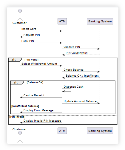
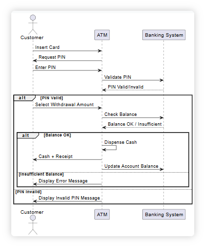
The diagram provided illustrates a robust interaction model for a Cash Withdrawal. Let’s walk through the components and the specific logic blocks depicted.
1. The Actors and Components
The diagram features three primary vertical lines, known as lifelines, representing the active participants in the system:
- Customer: Represented by a stick figure (UML Actor), this is the external user initiating the request.
- ATM: The hardware interface (User Interface) that mediates between the user and the backend.
- Banking System: The backend application responsible for logic, validation, and database updates.
2. The Interaction Flow
The diagram follows a strict top-to-bottom timeline:
- Authentication Phase: The Customer inserts a card, and the ATM requests a PIN. The Customer enters the PIN, which the ATM forwards to the Banking System for validation. The Banking System returns a
PIN Valid/Invalidstatus. - Transaction Phase: If the PIN is valid, the Customer selects a withdrawal amount.
- Validation & Execution: The ATM asks the Banking System to check the balance. The system returns
Balance OK / Insufficient. - Completion: If funds are available, the ATM dispenses cash and generates a receipt, while the Banking System updates the account balance.
Advanced Modeling Concepts: Alt and Opt Blocks
The most critical aspect of this diagram is how it handles conditional logic using Combined Fragments. In UML, these are represented by the rectangular frames labeled “alt” (alternative) and “opt” (optional).
The alt (Alternative) Fragment
The outer alt frame labeled [PIN Valid] represents a critical decision point. It indicates that the system behaves differently depending on the outcome of the PIN check:
- Condition 1: [Balance OK] If the check passes, the system executes the internal sequence: dispense cash, generate receipt, and update the database.
- Condition 2: [Insufficient Balance] If the check fails, the system executes a different path: display an error message to the customer.
The alt Fragment for PIN Failure
There is another alt fragment at the bottom of the diagram labeled [PIN Invalid]. This acts as a “guard” for the entire transaction. If the PIN check fails at the beginning, the system skips all withdrawal logic and immediately displays an “Invalid PIN Message” to the user.
Modernizing the Workflow with Visual Paradigm
Traditionally, creating these diagrams required manual drawing of lifelines and arrowheads, which was time-consuming and prone to formatting errors. This is where the integration of AI and tooling like Visual Paradigm revolutionizes the workflow.
- Start Simple: Instead of drawing boxes and lines, you can start with a text-based sketch or a simple description of the actors and interactions.
- Refine with AI: Using AI-powered refinement, you can expand a basic sketch into a detailed, fully compliant UML diagram. The tool automatically maps your text to MVC (Model-View-Controller) components, ensuring architectural best practices are met.
- Customize in VP Online: Once generated, the diagram can be opened in Visual Paradigm Online. Here, you can fine-tune the layout, add documentation, or integrate it with other UML diagrams like Class or Use Case diagrams.
This workflow ensures that your sequence diagrams are not just visual aids, but powerful tools for system architecture design that improve communication and reduce design errors.

 English
 Arabic
 Chinese (Simplified)
 Dutch
Dutch French
 German
 Italian
 Japanese
 Korean
 Portuguese
 Russian
 Spanish