


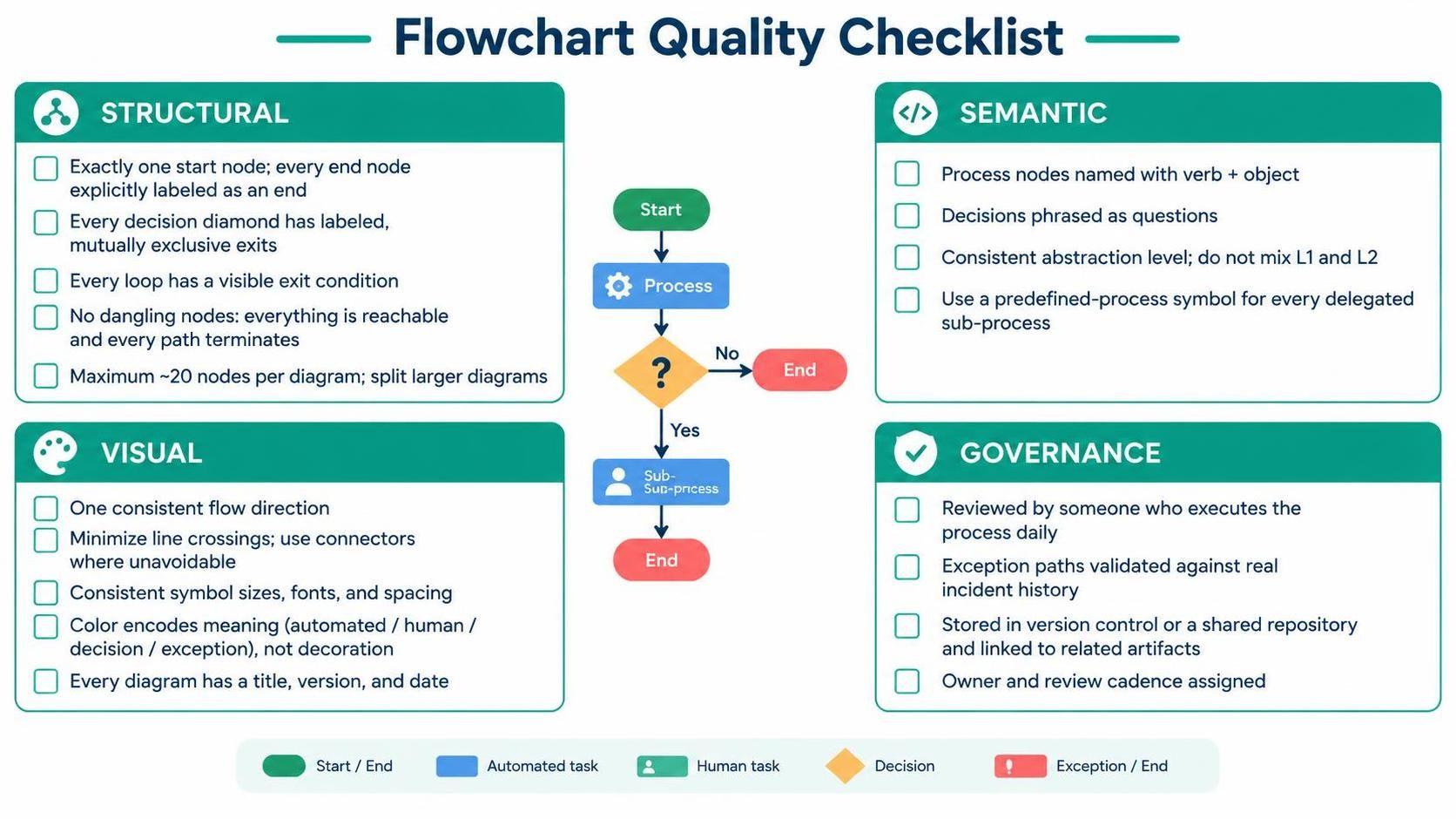
Creating a high-quality process diagram is often more about discipline than design flair. In the world of business process management, a visual representation that is confusing, ambiguous, or technically incorrect can lead to failed implementations and frustrated stakeholders. This tutorial explores the rigorous standards required for professional flowcharting, specifically tailored for the Visual Paradigm Flowchart Tool and its integration with AI-Assisted Diagram Generation.
We will break down the “Flowchart Quality Checklist” into four critical pillars: Structural Integrity, Semantic Clarity, Visual Consistency, and Governance. By adhering to these guidelines, you ensure that your diagrams are not just pretty pictures, but actionable blueprints for your organization.
1. Structural Integrity: The Skeleton of Your Diagram
The structural aspect of a flowchart is the foundation. If the logic does not hold together, the visual details are irrelevant. In Visual Paradigm, structural rules are often enforced by the diagramming engine, but the architect must ensure the logic is sound.
- Single Entry, Single Exit: Every diagram must begin with exactly one start node and ensure every path eventually leads to an explicitly labeled end node. This prevents “dangling nodes”—logic paths that disappear into the void.
- Decision Diamonds: Every decision point (diamond shape) must have labeled, mutually exclusive exits. For example, if a decision asks “Is the order valid?”, the exits should be “Yes” and “No.” Never leave an exit unlabeled.
- Loop Control: Any loop (a path that returns to a previous step) must have a visible exit condition. Infinite loops are a common pitfall in AI-assisted generation; you must manually verify that the “Yes” or “No” path eventually breaks the cycle.
- Complexity Management: A diagram with more than ~20 nodes becomes cognitively overwhelming. If your process exceeds this, split the diagram into sub-processes. Visual Paradigm supports this via the Predefined Process symbol.
2. Semantic Clarity: Naming and Abstraction
Semantics refer to the meaning behind the symbols. A process node is not just a box; it is an instruction. Poor naming conventions can lead to misinterpretation of the workflow.
Verb + Object Naming
Process nodes should always be named using a Verb + Object structure (e.g., “Validate Invoice” instead of just “Invoice”). This ensures the action is clear and the diagram is readable.
Abstraction Levels (L1 vs. L2)
A common mistake is mixing levels of abstraction (L1 and L2). A Level 1 diagram shows the high-level flow, while a Level 2 diagram drills down into the details of a specific step. Do not mix them. If you are at a high level, delegate the details to a sub-process symbol (often represented by a symbol with double borders or a specific icon in VP).
3. Visual Consistency: The User Interface of Logic
Visual consistency reduces cognitive load. If a user has to guess what a blue box means versus a red box, the diagram has failed.
- Flow Direction: Maintain a consistent flow direction, typically top-to-bottom or left-to-right. Avoid line crossings; if they are unavoidable, use connector symbols to keep the path clear.
- Symbol Standardization: Use consistent symbol sizes, fonts, and spacing. Visual Paradigm offers templates that automatically align these elements.
- Color Coding: Use color to encode meaning, not decoration. For example, use green for Start/End, blue for Automated tasks, and red for Exception paths. This allows a stakeholder to scan the diagram and instantly see where the system runs automatically versus where human intervention is required.
4. Governance: The Lifecycle of the Diagram
A diagram is a living document. It requires governance to remain accurate and useful over time.
- Validation: A chart must be reviewed by someone who executes the process daily. They are the only ones who know the “real” logic, including edge cases.
- Exception Paths: Validate exception paths against real incident history. Does your diagram account for the error that happened last month?
- Version Control: Store your diagrams in a shared repository or version control system. Every diagram should have a Title, Version, and Date.
Conclusion
By integrating these structural, semantic, visual, and governance rules into your workflow with Visual Paradigm, you transform a simple flowchart into a robust architectural artifact. Whether you are building it manually or guiding an AI, these standards ensure that your process models are accurate, maintainable, and ready for automation.

 English
 Arabic
 Chinese (Simplified)
 Dutch
 French
 German
 Italian
 Japanese
 Korean
 Portuguese
 Russian
 Spanish