


1. Introduction to UML
What is UML?
Unified Modeling Language (UML) is a used to design, analyze, and document software systems. It acts as a blueprint for software development, helping teams visualize the structure and behavior of a system before writing any code.
Why Use UML?
- Clarity: UML provides a clear, visual way to communicate complex systems to both technical and non-technical stakeholders.
- Collaboration: It .
- Efficiency: during development.
Who Uses UML?
- Software engineers
- Business analysts
- System architects
- Project managers
2. Types of UML Diagrams
UML diagrams are categorized into Structural and Behavioral diagrams.
A. Structural UML Diagrams
These diagrams represent the static aspects of a system, such as classes, objects, and components.
1. Class Diagram
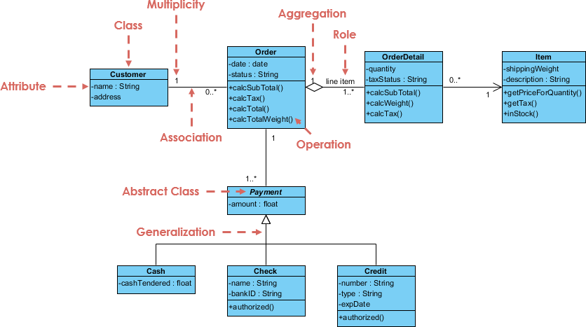
- Purpose: Shows the structure of a system by depicting classes, their attributes, methods, and relationships.
- Use Case: Essential for object-oriented design and analysis.
- Example: A class diagram for an e-commerce system might include classes like
User,Product, andOrder.
2. Composite Structure Diagram
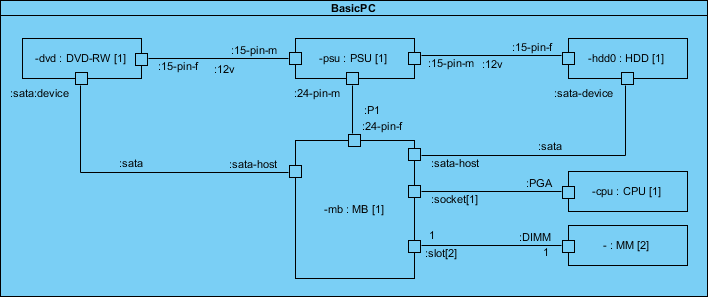
- Purpose: Represents the internal structure of a class and its interactions with other parts of the system.
- Use Case: Useful for modeling complex systems with interconnected components.
3. Object Diagram
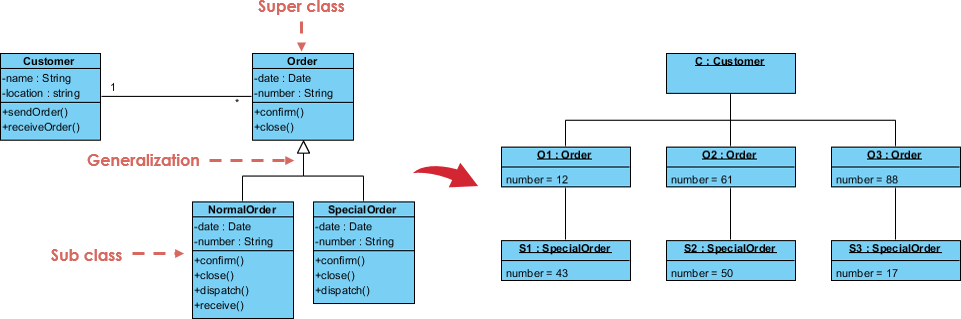
- Purpose: A , showing instances of classes and their relationships.
- Use Case: Helps visualize how objects interact in real-time scenarios.
4. Component Diagram
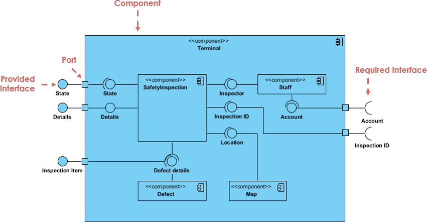
- Purpose: Illustrates how physical components (e.g., modules, libraries) are organized in a system.
- Use Case: Critical for understanding the implementation details of large systems.
5. Deployment Diagram
- Purpose: Shows the hardware and software components of a system and their distribution.
- Use Case: Used for planning system deployment across servers or devices.
6. Package Diagram
- Purpose: Organizes UML elements into logical groups (packages) and shows dependencies between them.
- Use Case: Helps manage large projects by grouping related classes or use cases.
B. Behavioral UML Diagrams
These diagrams represent the dynamic aspects of a system, such as interactions and workflows.
1. State Machine Diagram
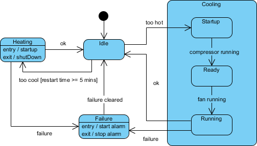
- Purpose: Models the behavior of a system as it transitions between states.
- Use Case: Useful for systems with complex workflows, such as order processing or user authentication.
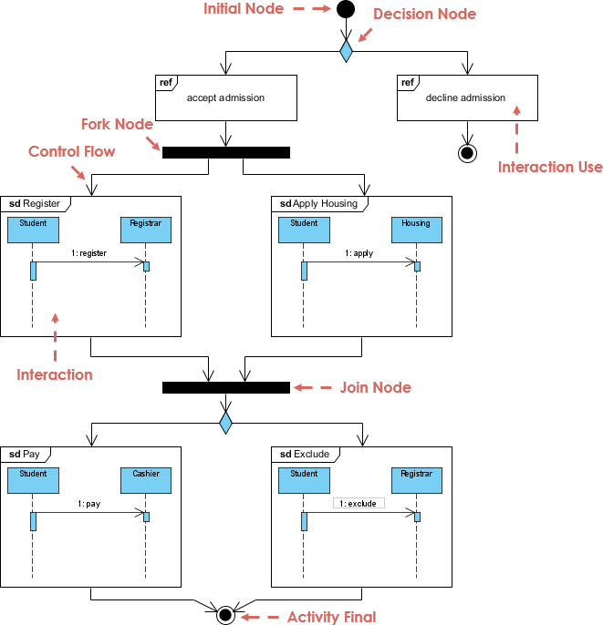
2. Activity Diagram
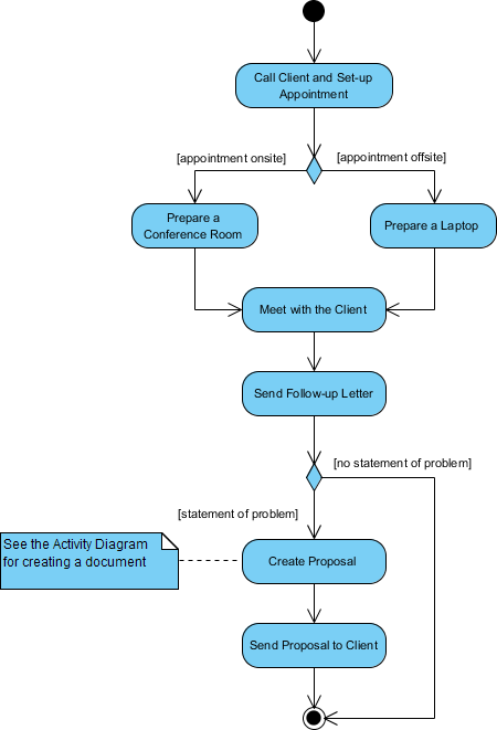
- Purpose: Illustrates the flow of activities or processes in a system.
- Use Case: Often used to model business processes or use case scenarios.
3. Use Case Diagram

- Purpose: Describes the functional requirements of a system and its interactions with external actors.
- Use Case: Provides a .
4. Sequence Diagram
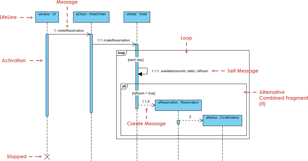
- Purpose: Shows how objects interact over time in a sequential order.
- Use Case: Helps document and validate system behavior.
5. Communication Diagram

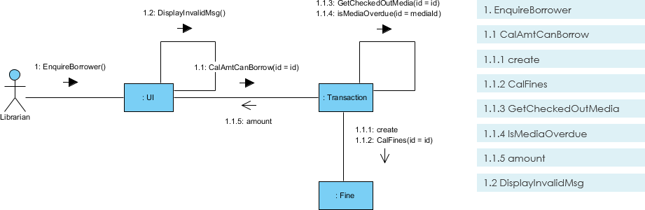 Purpose: Focuses on object interactions and message flow.
- Use Case: Similar to sequence diagrams but emphasizes object relationships.
6. Timing Diagram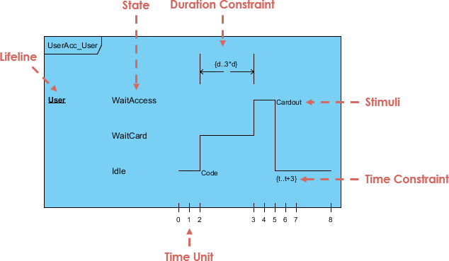
- Purpose: A .
- Use Case: Critical for real-time systems where timing is essential.
7. Interaction Overview Diagram
- Purpose: Provides a high-level view of interactions between system elements.
- Use Case: Useful for summarizing complex workflows.
3. UML 2.0 Additions
:
- Timing Diagram
- Communication Diagram
- Interaction Overview Diagram
- Composite Structure Diagram
It also expanded the ability to decompose systems into sub-components, making UML more flexible for modern software development methodologies like Agile.
4. Tools for Creating UML Diagrams
There are many tools available for creating UML diagrams, including:
- Visual Paradigm
- Lucidchart
- Draw.io
- Microsoft Visio
- IBM Rational Software Architect
5. Why Use Visual Paradigm AI Diagram Generator?
Key Benefits
- AI-Powered: Automates diagram creation, saving time and reducing errors.
- User-Friendly: Intuitive interface for both beginners and experts.
- Collaboration: Supports team collaboration with cloud-based sharing.
- Templates: Offers pre-built templates for all UML diagram types.
- Integration: Works seamlessly with popular development tools like JIRA and Confluence.
How to Use Visual Paradigm AI Diagram Generator
 Diagrams")
- Sign Up: Create an account on Visual Paradigm.
- Select Diagram Type: Choose the UML diagram you want to create (e.g., Class Diagram, Use Case Diagram).
- Use AI Assistance: Input your requirements, and let the AI generate a draft diagram.
- Customize: Edit the diagram to fit your specific needs.
- Export & Share: Save your diagram in various formats (PNG, SVG, PDF) and share it with your team.
6. Conclusion
UML diagrams are a powerful tool for designing, analyzing, and documenting software systems. By using tools like Visual Paradigm AI Diagram Generator, you can boost your productivity, reduce errors, and improve collaboration.
Next Steps
- Try creating a Class Diagram for a simple system using Visual Paradigm.
- Explore Use Case Diagrams to document functional requirements for your next project.
Would you like a step-by-step guide on creating a specific UML diagram? Let me know!
