


Embedded systems operate in environments where reliability is non-negotiable. A single logic error can lead to hardware damage, safety risks, or costly field failures. At the heart of many embedded control architectures lies the Finite State Machine (FSM). These diagrams provide a clear map of how a system behaves under various conditions. However, the visual representation is only as good as its validation. A diagram that looks correct on paper often hides logical gaps that only appear during runtime.
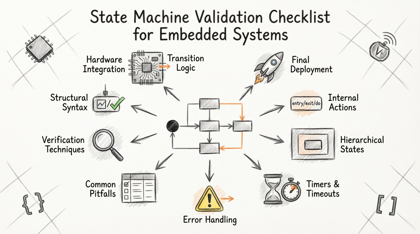
This guide provides a comprehensive checklist for validating UML State Machine Diagrams. It focuses on structural correctness, behavioral logic, and integration points. By following these steps, you ensure that the design phase translates accurately into executable code. We will cover syntax, transitions, actions, hierarchy, and error handling without relying on specific tools. The goal is to build a robust foundation for your embedded software.
1. Structural Integrity and Syntax ✅
Before analyzing logic, the diagram must adhere to the rules of UML state machine syntax. Invalid syntax leads to confusion and ambiguity during implementation. Every node and edge must be defined according to standard conventions.
- Initial Pseudostate: Ensure there is exactly one black filled circle representing the entry point of the machine. Systems should not start in undefined states.
- Final Pseudostates: Verify the presence of termination points. While some embedded systems run continuously, specific operations (like shutdown sequences) need defined exit paths.
- State Nodes: Every state must have a unique identifier. Avoid duplicate names within the same region to prevent ambiguity.
- Transitions: Every arrow must have a clear source and target. Floating transitions that do not connect to a state are invalid.
- Orthogonal Regions: If using concurrent states, verify that regions are properly partitioned. Signals must be routed correctly between parallel hierarchies.
- Labels: Ensure all transition labels follow the Event/Guard/Action syntax. Missing components can lead to implementation errors.
Validation Tip: Perform a static walk-through of the diagram path from the initial node to every reachable state. If any state cannot be reached from the start, it represents dead code or a design error.
2. Transition Logic and Guard Conditions 🔗
Transitions define how the system moves from one condition to another. In embedded systems, these moves are often triggered by hardware interrupts, sensor inputs, or internal timeouts. The logic governing these moves must be precise.
- Event Definition: Confirm that every event triggering a transition is defined elsewhere in the system architecture. An undefined event in a diagram implies a missing interface.
- Guard Clauses: Guards are boolean conditions that must evaluate to true for a transition to fire. Check that all guards use variables that are accessible at that state.
- Conflicting Transitions: Ensure that no two transitions from the same state are triggered by the same event without a guard to differentiate them. This creates ambiguity in execution order.
- Default Transitions: If a transition has no event (often called a default or implicit transition), it should only exist if the logic dictates an immediate move upon entry. These are rare and should be explicitly marked.
- Self-Transitions: Review self-loops carefully. They are valid for internal processing, but ensure they do not cause infinite loops if no action modifies the triggering condition.
- Priority: If multiple transitions are possible, verify the priority logic. Explicit guards should take precedence over implicit defaults.
Consider the scenario where a sensor fails. Does the transition to an error state occur immediately, or does it wait for a timeout? The diagram must reflect the desired timing behavior explicitly.
3. State Internal Actions and Invariants 🧠
States are not just placeholders; they represent active behaviors. Understanding what happens while the system resides in a specific state is critical for timing and resource management.
- Entry Actions: These execute once upon entering the state. Check for side effects. Do not perform blocking operations in entry actions that could delay other system processes.
- Exit Actions: These execute upon leaving the state. Ensure resources (like file handles, memory locks, or GPIO pins) are released here if they were acquired during the state.
- Do Activities: These represent ongoing behaviors while in the state. Verify that the duration of a Do activity is compatible with the system’s real-time constraints.
- Invariants: Some models allow invariants (conditions that must always be true while in the state). Validate that these conditions are mathematically possible given the entry conditions.
- Variable Scope: Ensure variables modified in a state are not overwritten unexpectedly in a concurrent orthogonal region.
- Reentrancy: If the system is reentrant, ensure state variables are not corrupted by interrupt handlers while a Do activity is running.
4. Hierarchical and Composite States 📊
Complex embedded systems often require nested states. This allows for modularity and reuse, but it introduces complexity regarding history and context preservation.
- Deep History: If a composite state has a history pseudo-state, verify the transition logic. Deep history restores the last active sub-state. Ensure the exit point logic matches the history type.
- Shallow History: Shallow history only restores the last active sub-state of the top level. Confirm that the design intent matches this behavior.
- Inherited Transitions: Transitions defined in a parent state apply to all child states. Review these to ensure they do not inadvertently trigger in child states where they are not intended.
- Override Logic: If a child state defines a transition with the same event as the parent, verify which one takes precedence. The child usually overrides the parent.
- State Activation: Ensure that when entering a composite state, the initial sub-state is correctly defined. The system should not wait for an event before initializing internal components.
- Termination: When exiting a composite state, verify the sequence of sub-state exits. Resources must be released in the reverse order of acquisition.
Validation requires tracing the path through the hierarchy. Does a transition from a deep child state correctly exit all parent levels if required?
5. Timers, Watchdogs, and Timeouts ⏱️
Embedded systems are time-sensitive. State machines often rely on timers to manage transitions that depend on duration rather than events.
- Timer Initialization: Verify that timers are started in the Entry Action of the state requiring the timeout.
- Timer Cancellation: Ensure timers are cancelled in the Exit Action if the state is left before the timeout occurs. This prevents spurious events from firing later.
- Timeout Events: The event generated by a timer must be unique. Do not reuse an event name for both a hardware interrupt and a software timeout unless the logic handles them distinctly.
- Watchdog Interaction: If the state machine feeds a hardware watchdog, ensure that transitions occur frequently enough to prevent a reset.
- Timeouts in Composite States: If a timer is active in a parent state, verify how it behaves when entering a child state. Does the timer pause, continue, or reset?
6. Error Handling and Recovery Paths 🚨
Real-world environments are noisy. Sensors fail, signals are lost, and hardware glitches occur. A robust state machine must account for these failures.
- Default Error State: Every machine should have a defined error state. If an unknown event is received, where does the system go?
- Recovery Logic: Define the path from the error state back to a safe operational state. Does it require manual intervention or automatic retry?
- Timeout on Error: If a transition fails, does the system retry immediately? If so, add a counter to prevent infinite loops.
- Resource Cleanup: In error states, ensure all allocated resources are returned. Do not leave pins floating or memory locked.
- Logging Points: Identify transition points where error codes should be recorded. This is vital for debugging field issues.
- Safe State: Define what “safe” means for the hardware. Is it powered down? Is it holding a position? The diagram must reflect this physical reality.
7. Common Pitfalls and Validation Criteria Table 📋
The following table summarizes common issues found during state machine validation and the criteria to resolve them.
| Category | Potential Issue | Validation Criteria |
|---|---|---|
| Logic | Unreachable States | Graph traversal confirms every state is accessible from the initial node. |
| Logic | Deadlocks | Ensure no state has no outgoing transitions and no internal loop. |
| Events | Event Name Collisions | Ensure event names are unique across the entire machine scope. |
| Actions | Blocking Operations | Entry/Exit actions must return control to the scheduler quickly. |
| Timing | Missing Reset | Verify all timers and counters are reset upon state entry. |
| Integration | Interface Mismatch | Event names in diagram must match function signatures in code. |
| History | History Loss | Verify deep history pseudo-states correctly restore sub-state context. |
| Resources | Resource Leaks | Every allocation in Entry must have a corresponding deallocation in Exit. |
8. Verification Techniques and Documentation 🔍
Validation does not end with the diagram. It extends into the verification phase where the model is tested against requirements.
- Model Checking: Use formal methods to prove that certain states (like error states) are reachable or unreachable under specific constraints.
- Simulation: Run the diagram in a simulation environment before deployment. Feed synthetic events to verify the output sequence.
- Code Generation: If generating code from the model, ensure the generated code matches the logic. Check for missing guards or ignored actions.
- Traceability Matrix: Link each state and transition to a specific requirement ID. This ensures nothing is built without justification.
- Peer Review: Have a colleague review the diagram. A fresh pair of eyes often catches logic flows that the author missed.
- Version Control: Treat diagrams as code. Maintain version history to track changes in logic over time.
9. Integration with Hardware and Middleware 📡
The state machine does not exist in a vacuum. It interacts with drivers, interrupts, and communication stacks.
- Interrupt Latency: Ensure the state machine can handle the latency of incoming interrupts without missing events.
- Context Switching: If the state machine runs in an RTOS, verify that the state is preserved correctly across context switches.
- Communication Protocols: If the state machine manages a protocol (like UART or CAN), validate the buffer handling logic within the states.
- Power Management: If the system sleeps, ensure the state machine context is saved and restored accurately upon wake-up.
- Signal Debouncing: If hardware inputs are used as events, the diagram should account for debouncing logic either in the state or the driver.
10. Final Validation Steps Before Deployment 🚀
Before releasing the design for implementation, perform a final audit.
- Confirm that all variables used in guards are initialized before the first state is entered.
- Check that the maximum stack usage does not exceed the limit during the deepest nested state transition.
- Verify that the error state is logged to non-volatile memory for post-mortem analysis.
- Ensure that the diagram documentation is updated to reflect any changes made during the design phase.
- Run a static analysis tool if available to check for syntax errors in the model definition.
Validating state machine diagrams is a discipline that blends theoretical rigor with practical engineering. It requires attention to detail at every node and edge. By adhering to this checklist, you reduce the risk of logical bugs and improve the maintainability of your embedded system. A well-validated diagram serves as a single source of truth, guiding implementation and testing with clarity. This approach ensures that the final product performs reliably in the field, meeting the demands of safety and performance without requiring constant patches or recalls.
Focus on the clarity of the model, the precision of the transitions, and the robustness of the error paths. These elements form the backbone of a dependable embedded architecture. When the diagram is sound, the code follows naturally, and the system behaves as intended.
