


Embedded systems rely on logic that responds to events in real-time. A state machine diagram serves as the blueprint for this logic. It defines how a system behaves under different conditions. For beginners, creating these diagrams is often more complex than it appears. A small error in the design phase can lead to significant bugs in the final hardware. This guide outlines the frequent mistakes made during the design process.
Designing a finite state machine requires precision. You are mapping out every possible condition the device can encounter. If the map is incomplete, the device may enter an undefined state. This is often where failures occur. In embedded contexts, memory is limited. Complexity must be managed carefully. We will explore the specific areas where designs typically fail.
🧠 Understanding the Core Components
Before identifying errors, one must understand the building blocks. A state machine consists of states, transitions, events, and actions. Each element plays a critical role in the system’s behavior.
- States: Represent a condition of the system. For example, a motor might be Off, Running, or Error.
- Transitions: The movement from one state to another. This is triggered by an event.
- Events: Signals that cause a transition. This could be a button press or a sensor reading.
- Actions: Operations performed when entering or exiting a state.
When these components are not clearly defined, the resulting code becomes difficult to maintain. Ambiguity in the diagram translates to ambiguity in the code.
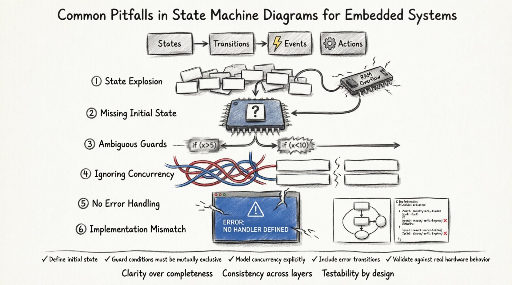
⚠️ Pitfall 1: The State Explosion Problem
One of the most common issues is creating too many states. Beginners often try to make a separate state for every unique configuration. In software, this is manageable. In embedded systems, memory is a strict constraint.
Why It Matters
If you have 20 states, you need 20 unique identifiers in your code. If you have 100 states, the lookup table becomes large. This increases the code footprint. It also increases the processing time required to determine the current state.
- Memory Usage: Each state may require storage for variables. Too many states consume RAM.
- Execution Speed: Checking the current state against a large list takes time.
- Maintainability: Updating logic for 50 states is harder than updating logic for 5 states.
The Solution
Group related states together. Use composite states or hierarchical designs. Instead of having a state for Motor On, Speed 50% and Motor On, Speed 100%, have a single Motor On state with a variable for speed.
🔄 Pitfall 2: Missing Initial State Definition
Every state machine must have a defined starting point. When power is applied to a microcontroller, the system boots up. If the state machine does not specify the initial state, the device might start in an invalid condition.
Consequences of Omission
- Undefined Behavior: The hardware might power up with pins in a high-impedance state or random logic levels.
- Hardware Damage: If a motor driver is active immediately upon boot, it could damage the load.
- Unpredictable Outputs: Sensors might read garbage values if they are not initialized before the first transition.
Always mark the entry point with a solid circle. Ensure the initial state sets all variables to known safe values. This includes GPIO pins, timers, and communication buffers.
🚦 Pitfall 3: Ambiguous Transition Guards
Guards are conditions that must be true for a transition to occur. Beginners often write guards that overlap. If two transitions leave the same state and have overlapping conditions, the system does not know which path to take.
Example Scenario
Imagine a state Idle. Two events can occur:
- Transition A: Event =
Button Press, Guard =System Ready - Transition B: Event =
Button Press, Guard =System Ready
Both conditions are true. The machine cannot decide. This creates a race condition in the implementation.
Better Practices
Ensure guards are mutually exclusive for the same event. If the logic is complex, use a priority mechanism. Document the priority explicitly. In hardware, this might mean checking one sensor before another. In software, this means ordering if-else blocks correctly based on the diagram.
🧩 Pitfall 4: Ignoring Concurrency and Orthogonal Regions
Complex embedded systems often run multiple processes simultaneously. A single state machine cannot always represent this. Beginners often try to force concurrency into a single flat state machine.
The Problem
Trying to model independent processes in one diagram leads to a tangled web of transitions. For example, a system might need to monitor a temperature sensor while simultaneously controlling a display. These two tasks are independent.
The Solution
Use orthogonal regions. These are independent state machines that run in parallel. The diagram should show a composite state with multiple sub-regions. This clarifies that the temperature logic does not block the display logic.
- Region 1: Sensor Monitoring Loop.
- Region 2: User Interface Loop.
- Region 3: Communication Handler.
This structure reduces the number of transitions required. It makes the diagram cleaner and the code modular.
📉 Pitfall 5: Lack of Error Handling States
Designs often focus on the happy path. They assume everything works perfectly. In embedded systems, hardware fails. Sensors drift. Power fluctuates.
Why Error States Are Critical
If an unexpected event occurs, the system must handle it gracefully. Without an error state, the system might hang or loop indefinitely. This is known as a deadlock.
- Timeouts: If a communication packet does not arrive, the system should time out.
- Invalid Inputs: If a user enters a code that does not exist, the system should reject it.
- Hardware Faults: If a motor stalls, the system should stop and alert the user.
Every major flow should have a path to a safe state. This state should be designed to recover or to shut down safely.
🧪 Pitfall 6: Implementation Mismatch
The diagram is only as good as the code that implements it. Beginners often create a complex diagram but implement it poorly. This creates a disconnect between design and reality.
Common Mismatches
- State Variables: The diagram shows states, but the code uses boolean flags for everything.
- Event Queue: The diagram assumes immediate processing. The code uses a queue that delays events.
- Entry/Exit Actions: The diagram lists actions, but the code places them in the transition logic instead.
This mismatch makes debugging difficult. If the diagram says the system is in State A, but the code says State B, the logic breaks. Always map the diagram elements directly to code structures.
📋 Checklist for Validation
Before finalizing the design, run through this checklist. It helps identify gaps in the logic.
| Check Item | Question to Ask | Impact of Failure |
|---|---|---|
| Initial State | Is there a single entry point? | Unpredictable boot behavior |
| Termination | Are there defined exit points? | Resource leaks or hangs |
| Guards | Are conditions mutually exclusive? | Race conditions |
| Events | Are all events handled? | Unhandled interrupts |
| Memory | Is the state count feasible? | Heap overflow or stack issues |
| Concurrency | Are parallel tasks separated? | Blocking execution flow |
🔍 Debugging State Machines
Once the code is running, debugging becomes the priority. Since state machines are event-driven, standard debugging tools can be tricky.
Logging Strategies
Implement a logging mechanism that records state changes. Every time the system transitions, write the current state, the event that caused it, and the resulting state to a buffer. This allows you to replay the sequence of events after a crash.
- Verbose Mode: Enable detailed logging during development.
- Trace Buffers: Use circular buffers to store recent history without consuming too much RAM.
- Visual Debuggers: If available, use tools that highlight the active state on a screen.
Simulation
Run the logic on a PC before deploying to hardware. This allows you to test edge cases without risking the physical device. Create a test harness that feeds events into the state machine logic and verifies the outputs.
📝 Documentation and Maintenance
A state machine diagram is a living document. It changes as requirements change. If the code changes but the diagram does not, the project becomes unmaintainable.
- Version Control: Keep the diagram in version control alongside the code.
- Change Logs: Document why a transition was added or removed.
- Standardization: Use consistent notation for states and events across the entire project.
When a new developer joins the team, the diagram is their primary reference. If it is outdated, they will write code that conflicts with the intended design.
🛠️ Handling Interrupts and Timing
Embedded systems rely heavily on interrupts. A state machine must interact with these correctly. A common mistake is trying to process interrupts directly inside the state machine logic.
Best Practice
Interrupts should set flags or signal events. The main loop or the state machine should check these events. Never perform heavy processing inside an interrupt service routine. This blocks other critical tasks.
- Event Signaling: Interrupts trigger the event that causes the transition.
- Event Queueing: If events happen faster than the processor, queue them.
- Atomic Operations: Ensure state checks are atomic to prevent corruption during interrupt handling.
This separation of concerns ensures the system remains responsive. The state machine handles logic, and the interrupt layer handles hardware signals.
🎯 Summary of Design Principles
Building robust embedded systems requires discipline. The state machine diagram is the foundation. Avoiding the pitfalls listed here ensures stability.
- Keep the state count low to save memory.
- Define the initial state clearly.
- Ensure transition guards do not overlap.
- Use orthogonal regions for independent processes.
- Include error handling states.
- Match the implementation exactly to the diagram.
- Validate with logging and simulation.
By following these guidelines, you create a system that is predictable and reliable. The complexity of the hardware does not matter if the logic is sound. A well-designed state machine simplifies the code and makes future updates easier.
🚀 Moving Forward
As you gain experience, you will find patterns in your designs. You will recognize when a state machine is too complex and needs refactoring. You will learn to balance performance with readability. This guide provides the foundation for that journey.
Focus on clarity. A diagram should be readable by a human, not just a compiler. If you can explain the logic to a colleague using the diagram, you have succeeded. If you have to write code comments to explain the diagram, it is too complex. Refine the design until the logic speaks for itself.
Remember that embedded systems are safety-critical in many applications. A bug in a medical device or an automotive control system can have serious consequences. Rigorous design practices protect the end user. Invest time in the planning phase. It saves time during the debugging phase.
Continue to study UML standards. They provide a common language for engineers. Adhering to these standards ensures that your diagrams are understood by anyone who knows the specification. This universality is a key benefit of using state machine diagrams in professional development.
