


Robotics systems require robust logic to manage complex behaviors reliably. A Finite State Machine (FSM) provides a structured way to model the motion control logic of autonomous agents. Using Unified Modeling Language (UML) state diagrams, engineers can visualize the lifecycle of a robot’s operation. This guide details the process of creating an FSM for a motion controller, ensuring safety, determinism, and maintainability.
🧠 Understanding FSM in Robotics
A Finite State Machine is a computational model used to design computer programs and digital logic circuits. In robotics, it dictates how a machine reacts to inputs based on its current condition. The motion controller is the heart of the robot, deciding when to move, stop, or pause.
Key benefits of using an FSM include:
- Clarity: Visual representation makes complex logic easier to understand.
- Modularity: States can be developed and tested independently.
- Debugging: Errors can be traced to specific state transitions.
- Scalability: New behaviors can be added without rewriting the core logic.
🔍 Core Components of a State Machine
Before designing the diagram, one must understand the building blocks. Each element serves a specific purpose in the motion control flow.
1. States
A state represents a condition during which the system waits for an event or performs an action. In motion control, common states include:
- IDLE: The robot is powered on but stationary.
- MOTORIZATION: Motors are receiving power to move.
- STOPPING: The robot is decelerating to a halt.
- ERROR: An exception occurred, requiring intervention.
2. Transitions
A transition is the movement from one state to another. It is triggered by an event. For example, a “Start Command” event might trigger a transition from IDLE to MOTORIZATION.
3. Events
Events are the triggers that cause transitions. They can be:
- External: User input, button presses, or remote commands.
- Internal: Timer expirations, sensor thresholds, or internal logic flags.
4. Actions
Actions are code executed when entering or exiting a state.
- Entry Action: Code run immediately upon entering the state (e.g., initializing motor PWM).
- Exit Action: Code run immediately upon leaving the state (e.g., cutting power to motors).
- Transition Action: Code run during the transition itself.
📐 Step-by-Step Design Process
Designing an FSM requires a systematic approach. Follow these steps to create a reliable motion controller diagram.
Step 1: Define the Scope
Identify the specific robot type. Is it a wheeled vehicle, a robotic arm, or a drone? The motion requirements dictate the states. For a wheeled mobile robot, focus on navigation and obstacle avoidance.
Step 2: Identify Initial and Final States
Every machine must have a starting point. Typically, the POWER_ON state is the initial state. Determine if there is a hard stop state where the robot cannot proceed without manual reset.
Step 3: List All Possible States
Create a comprehensive list of every condition the robot can be in. Avoid overly granular states, but ensure safety-critical conditions are captured. Consider:
- Navigation states (Forward, Backward, Left, Right).
- Operational states (Active, Paused, Charging).
- Failure states (Sensor Fault, Battery Low, Motor Overheat).
Step 4: Define Transitions and Guards
Draw lines connecting states. Label them with the event that triggers the move. Use guards to specify conditions where a transition only occurs if a criterion is met. For instance, a transition to MOVING might have a guard [battery_level > 20%].
Step 5: Specify Entry and Exit Actions
Detail the code or logic executed during state changes. This ensures hardware is configured correctly for each mode. For example, entering MOVING might enable encoders, while exiting it disables them.
🚀 Case Study: Autonomous Mobile Robot (AMR)
Let us apply these concepts to an Autonomous Mobile Robot tasked with warehouse navigation. The goal is to move from point A to point B while avoiding obstacles.
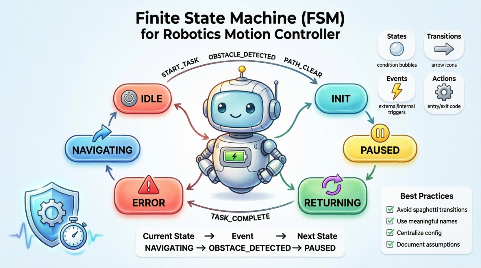
Primary States
- INIT: System boot and sensor calibration.
- IDLE: Waiting for a task assignment.
- NAVIGATING: Moving towards the target waypoint.
- PAUSED: Temporarily halted due to dynamic obstacles.
- RETURNING: Moving back to the charging station.
- CHARGING: Docked and recharging.
- ERROR: Critical failure requiring human assistance.
Scenario Walkthrough
- Start: Robot powers up in
INIT. - Task Received: Event
NEW_TASKmoves robot toIDLE. - Execution: Event
START_MOVEtransitions toNAVIGATING. - Obstacle: Event
OBSTACLE_DETECTEDtriggersPAUSED. - Clear Path: Event
PATH_CLEARreturns toNAVIGATING. - End Task: Event
TASK_COMPLETEtriggersRETURNING.
📊 Creating the Transition Table
A transition table is often used alongside the diagram to ensure no state is missing. It lists every possible input for every state.
| Current State | Event | Condition (Guard) | Next State | Actions |
|---|---|---|---|---|
| IDLE | START_TASK | Battery > 10% | NAVIGATING | Enable Motors, Set Target |
| IDLE | LOW_BATTERY | Battery < 10% | RETURNING | Abort Task, Route to Dock |
| NAVIGATING | OBSTACLE | Distance < 0.5m | PAUSED | Stop Motors, Log Event |
| NAVIGATING | GOAL_REACHED | Position = Target | IDLE | Disable Motors, Send Report |
| PAUSED | PATH_CLEAR | Distance > 1.0m | NAVIGATING | Resume Motors |
| ERROR | RESET | Admin Auth | IDLE | Clear Fault Flags |
⚙️ Handling Concurrency and Timers
Real-world robotics often requires concurrent states. A robot might be NAVIGATING while simultaneously monitoring BATTERY_STATUS. UML supports hierarchical states or orthogonal regions to handle this.
Timers in Motion Control
Timers are essential for time-based logic. Examples include:
- Timeout: If a task takes too long, trigger a stop.
- Delay: Wait 2 seconds before starting after a stop.
- Pulse: Blink a status LED every 500ms.
When using timers, ensure the FSM resets them correctly upon exiting a state to prevent unintended triggers later.
🛡️ Error Handling and Safety
Safety is paramount in robotics. The FSM must account for failures gracefully.
1. Fault Detection
Continuous monitoring is required. If a motor driver reports an overcurrent, the system must immediately transition to an ERROR state.
2. Recovery Logic
Not all errors are fatal. A temporary sensor glitch might require a RETRY state. A hard hardware failure requires a STOP state.
3. Watchdog Timers
Implement a software watchdog outside the FSM. If the FSM hangs or fails to update, the watchdog resets the controller. This prevents the robot from running away or stuck in a loop.
🧪 Debugging and Validation
Once the diagram is designed, validation is necessary before deployment.
- Code Walkthrough: Review the logic manually to check for unreachable states.
- Simulation: Run the logic in a virtual environment to test edge cases.
- Unit Testing: Write tests for each state transition individually.
- Integration Testing: Test the FSM with real hardware sensors and actuators.
🔧 Best Practices for Motion Control Logic
To ensure long-term maintainability, adhere to these guidelines.
1. Avoid Spaghetti Transitions
Do not create a dense web of arrows. If a state has too many incoming transitions, consider breaking it down into sub-states.
2. Use Meaningful Names
Name states and events clearly. STATE_1 is confusing. MOVING_FORWARD is descriptive.
3. Centralize Configuration
Keep parameters like speed limits or turn angles in a configuration file, not hard-coded in the state actions.
4. Document Assumptions
Write down what each state assumes about the environment. If NAVIGATING assumes sensors are working, document that dependency.
5. Handle Asynchronous Events
Sensors may trigger events at any time. Ensure the FSM can queue events or handle interrupts without data loss.
📝 Summary of Implementation Steps
Implementing the FSM involves translating the design into code.
- Define Enumerations: Create a list of all states and events in the codebase.
- Create State Machine Class: Initialize variables to track current state and pending events.
- Implement Transition Logic: Use a switch-case or dictionary map to handle state changes.
- Execute Actions: Call specific functions for entry, exit, and transition actions.
- Loop Structure: Ensure the main loop calls the FSM update function repeatedly at a fixed frequency.
🔮 Future Considerations
As robotics evolves, FSMs may integrate with higher-level planners. While FSMs handle low-level motion, machine learning models might handle high-level decision making. The interface between these systems should be well-defined. For instance, the FSM provides a “Ready” signal when the robot is stable enough to accept a new high-level command.
🛠️ Final Thoughts on Design
Designing a Finite State Machine for a motion controller is a foundational task in robotics engineering. It brings order to chaos, ensuring that the robot behaves predictably under all conditions. By following the structured approach outlined here, teams can build systems that are safe, efficient, and easy to maintain. The key lies in balancing complexity with clarity, ensuring the model remains a useful tool rather than a source of confusion.
Focus on the specific needs of the motion controller. Whether it is a simple line follower or a complex autonomous vehicle, the principles of state, transition, and action remain constant. With careful planning and rigorous testing, the FSM becomes the backbone of reliable robotic operation.
