


Embedded systems operate in a world of strict constraints. Every cycle counts, and every byte of memory matters. In this environment, code clarity is not just a nice-to-have; it is a requirement for stability and safety. One of the most powerful tools to achieve this clarity is the State Machine Diagram within the Unified Modeling Language (UML) framework. These diagrams provide a visual blueprint for how software behaves over time in response to events.
Understanding how to model logic using state machines is fundamental for designing robust embedded applications. Whether you are building a simple thermostat or a complex automotive control unit, visualizing the lifecycle of your software helps prevent logical errors before they become hardware failures. This guide breaks down the essential concepts, components, and construction methods for creating effective State Machine Diagrams.
🧠 What is a State Machine Diagram?
A State Machine Diagram, often referred to as a Statechart or Activity Diagram with state focus, represents the dynamic behavior of a system. Unlike a flowchart, which maps a linear sequence of steps, a state machine maps the conditions under which a system exists at any given moment. It answers the question: “What does the system look like right now, and what changes that look?”
In the context of embedded systems, this is often synonymous with a Finite State Machine (FSM). The “Finite” part is crucial. It means the system can only be in one specific state at any given time. It cannot be both “Running” and “Stopped” simultaneously. This distinct separation simplifies debugging and testing.
🔑 Core Components of a State Machine
To build a diagram, you must understand the vocabulary. Every valid diagram is constructed from a specific set of building blocks. These elements define the structure and logic of the system.
1. States
A state represents a condition during the life of an object or system. It is a period of time where the system waits for an event. Visually, states are typically drawn as rounded rectangles.
- Simple State: A basic state with no internal structure (e.g., “Idle”, “Active”).
- Composite State: A state that contains other sub-states (e.g., “Processing” might contain “Reading Sensor” or “Writing Data”).
- Initial State: The starting point of the machine. Usually depicted as a solid circle.
- Final State: The termination point. Usually depicted as a solid circle within a larger circle.
2. Transitions
A transition is the movement from one state to another. It represents the change in the system’s status. Transitions are drawn as arrows connecting two states.
- Transitions are instantaneous. The system does not spend time “in transit”.
- They are triggered by specific events.
- They may include conditions (guards) that must be met for the move to happen.
3. Events
An event is a significant occurrence that triggers a transition. In embedded systems, events are often:
- Hardware interrupts (e.g., a button press).
- Timeouts (e.g., a timer expires).
- Software signals (e.g., data received from a network).
- State entry/exit completions.
4. Actions
Actions are the work performed by the system. They are associated with states or transitions. There are three primary types of actions:
- Entry Action: Code that runs immediately when the system enters a state.
- Exit Action: Code that runs immediately when the system leaves a state.
- Do Action: Code that runs continuously while the system remains in the state (e.g., a motor control loop).
5. Guard Conditions
A guard condition is a boolean expression that determines whether a transition can occur. It acts as a gatekeeper. Even if an event occurs, the state will not change unless the guard evaluates to true.
- Example:
if (batteryLevel > 20%) - Example:
if (temperature < 100)
📊 Component Comparison Table
To clarify the distinctions between these components, refer to the table below.
| Component | Visual Symbol | Function | Timing |
|---|---|---|---|
| State | Rounded Rectangle | Represents a condition | Duration (can be long or short) |
| Transition | Arrow | Connects two states | Instantaneous |
| Event | Text on Arrow | Triggers the transition | Occurrence Point |
| Guard | Text in Brackets [] | Validates the transition | Before transition executes |
| Action | Text on Arrow or in State | Executes logic | During Entry, Exit, or Stay |
🛠️ Step-by-Step Guide to Building a Diagram
Creating a diagram from scratch can feel overwhelming. Follow this structured process to ensure logical consistency and completeness.
Step 1: Identify the System Scope
Define what the state machine controls. Is it the entire device, or just a specific module? Keeping the scope manageable is vital. For example, do not try to model the entire car electronics system in one diagram. Focus on the "Engine Control Unit" or the "Power Management Module" specifically.
Step 2: List the States
Brainstorm every possible condition the system can be in. Ask yourself: "What are the distinct modes of operation?"
- Power Off
- Booting
- Standby
- Active Operation
- Error Recovery
Ensure these states are mutually exclusive. The system should not be in two states at once.
Step 3: Define the Events
What causes the system to move between the states you listed in Step 2? Look at the inputs.
- User Input (Button Press)
- External Signal (Sensor Data)
- Internal Timer
- System Error
Step 4: Draw the Transitions
Connect the states using arrows. Label each arrow with the event that triggers it. If a transition requires a condition, add the guard condition in brackets.
- Draw a solid circle for the start point.
- Draw a double circle for the end point.
- Connect the Start point to the initial operational state.
Step 5: Add Actions
Specify what happens inside each state. If entering the "Active" state requires initializing a variable, write that as an Entry Action. If leaving the "Active" state requires saving data, write that as an Exit Action.
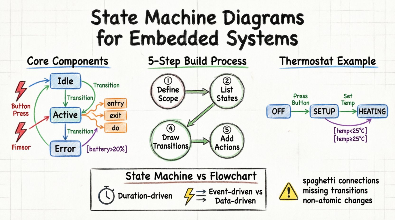
🌡️ Practical Example: Thermostat Logic
Let us apply these concepts to a classic embedded scenario: a digital thermostat. This example demonstrates how to manage temperature control logic cleanly.
Scenario Description
The thermostat has two main modes: Heating and Cooling. It starts in an "Off" state. When a button is pressed, it enters "Setup" mode. If the temperature drops below a set point, it engages "Heating". If the temperature rises above a set point, it engages "Cooling".
Diagram Construction
Here is how the states and transitions break down for this system.
- State: OFF
- Entry Action: Turn off heater, turn off fan.
- Event: Button_Press
- Transition: Move to "SETUP".
- State: SETUP
- Entry Action: Display current temperature.
- Event: Temp_Decrease
- Transition: Lower target temp.
- Event: Button_Press (Hold)
- Transition: Move to "HEATING".
- State: HEATING
- Entry Action: Set heater pin HIGH.
- Do Action: Read temperature sensor every 5 seconds.
- Guard Condition: If (currentTemp >= targetTemp)
- Transition: Move to "OFF".
This structure ensures that the heater never turns on unless the system is explicitly in the "Heating" state. It also prevents conflicting actions, such as turning the heater on and the fan on simultaneously in a way that causes a short circuit.
⚠️ Common Pitfalls in State Design
Even experienced engineers can introduce complexity that makes state machines difficult to maintain. Be aware of these common issues.
1. The "Spaghetti State"
Avoid creating a diagram where every state connects to every other state. If you see a web of crossing arrows, the logic is likely too complex. Use composite states to group related behavior. For instance, instead of having "Error_1", "Error_2", and "Error_3" as separate top-level states, group them under a parent "Error" state with sub-states.
2. Missing Transitions
What happens if an event occurs in a state where it is not defined? In embedded systems, this often leads to a crash or undefined behavior. Always define a "catch-all" transition or ensure the system handles unexpected events gracefully, perhaps by moving to a default "Error" state.
3. Non-Atomic Transitions
Ensure that transitions happen as a single logical unit. If a transition involves changing multiple variables, they should all be updated before the system enters the next state. Do not allow the system to linger in a partially updated state.
4. Overusing "Do" Actions
While "Do" actions are useful for continuous monitoring, overusing them can make the state machine appear to be a continuous loop rather than a state-based model. Reserve "Do" actions for tasks that must run repeatedly while the system waits for an event, such as sensor polling.
🔍 Deep Dive: Guard Conditions vs. Logic in Actions
One of the most frequent questions in embedded design is where to place logic: in the guard condition or in the action itself.
- Guard Conditions: Use these for simple boolean checks that determine if a transition happens. Keep them lightweight. If the logic is complex, it slows down the event processing.
- Actions: Use these for the actual work done during the transition. If you need to calculate a value or update a variable, do it in the action.
Consider a scenario where a transition occurs only if a battery level is sufficient. The guard should check if (battery > 10%). If true, the action might be turnOnMotor(). This separation makes the diagram readable: the arrow tells you when it happens, and the label tells you what it does.
🧪 Testing and Validation
Once the diagram is complete, how do you know it works? Model-Based Design allows you to test the diagram before writing a single line of C or C++ code.
1. Path Coverage
Trace every possible path through the diagram. Can you reach every state? Can you reach every transition? Ensure there are no dead ends where the system gets stuck.
2. Event Sequence Testing
Simulate a sequence of events. For example, press Button, Wait 5 seconds, Press Button again. Does the state change as predicted? This helps verify that the timing and event ordering are correct.
3. Edge Cases
Test the boundaries. What happens if the temperature is exactly at the threshold? What happens if two events occur simultaneously? Ensure the state machine handles these edge cases without crashing.
🔄 State Machine vs. Flowchart
Beginners often confuse State Machine Diagrams with Flowcharts. While both use shapes and arrows, they serve different purposes.
| Feature | State Machine Diagram | Flowchart |
|---|---|---|
| Focus | System behavior over time | Algorithm execution flow |
| Duration | States have duration (time spent) | Steps are instantaneous |
| Input | Events (External/Interrupts) | Input Data |
| Reusability | High (States can be reused) | Low (Linear path) |
| Best For | Embedded Control, UI Logic | Calculations, Data Processing |
For embedded systems, the State Machine is superior for control logic because it explicitly handles the waiting periods and event responses that define real-time systems.
📝 Best Practices for Embedded State Machines
To maintain code quality and system reliability, adhere to these guidelines when implementing the logic derived from your diagram.
- Naming Conventions: Name your states and events clearly. Use PascalCase for states (e.g.,
StateIdle) and CamelCase for events (e.g.,OnButtonPressed). - State Separation: Keep states small. If a state contains too much logic, split it into sub-states.
- Event Handling: Use an event queue to manage incoming signals. This ensures events are processed in order and prevents race conditions.
- State Variables: Keep track of the current state in a dedicated variable. Avoid using flags to determine state; use the state variable itself.
- Documentation: Keep the diagram up to date. If the code changes, the diagram must reflect that change. An outdated diagram is more dangerous than no diagram at all.
🚀 Conclusion
Designing embedded software requires precision and foresight. State Machine Diagrams provide the visual foundation needed to achieve this precision. By breaking down complex behavior into discrete states and well-defined transitions, you create systems that are easier to understand, test, and maintain.
Start small. Model a simple function first. As you become comfortable with the components—states, transitions, events, and guards—you will find that these diagrams become indispensable tools in your engineering toolkit. They transform abstract logic into a tangible map, guiding your code through the complexities of real-world hardware interaction.
Remember, the goal is not just to write code that works, but to design systems that are robust against the unpredictable nature of the physical world. With a solid state machine foundation, your embedded projects will stand on firmer ground.
