


In the architecture of complex software systems, control flow is paramount. When designing systems that react to events, sequences, or inputs, State Machine Diagrams provide the blueprint. These diagrams model the behavior of an object or system over time. They are essential for defining how a system transitions between conditions in response to stimuli.
While the concept of a machine changing states is intuitive, the mathematical and logical underpinnings vary significantly across models. Specifically, the distinction between Finite State Machines (FSM), Moore Machines, and Mealy Machines determines how outputs are generated and how responsive a system feels to external inputs. This guide dissects these models within the context of UML (Unified Modeling Language), offering a deep dive into their structures, behaviors, and practical applications.
Understanding the Finite State Machine (FSM) 🧱
At the core of this discussion lies the Finite State Machine. An FSM is a computational model used to design computer programs and sequential logic circuits. It can be in one of a finite number of states at any given time.
Core Components of an FSM
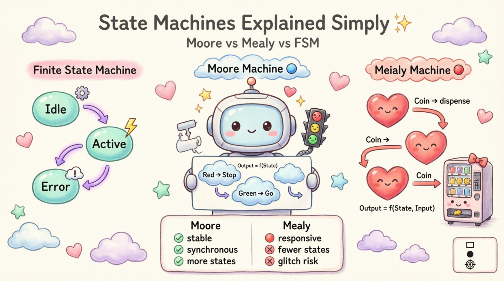
- States: Distinct conditions or configurations the system can be in (e.g., Idle, Active, Error).
- Transitions: The movement from one state to another triggered by specific events.
- Initial State: The starting point of the system lifecycle.
- Final State: The termination point of the process.
- Events: Inputs that cause a transition to occur.
In UML, an FSM is often visualized as a State Machine Diagram. These diagrams capture the dynamic behavior of a class or system. They are distinct from sequence diagrams or activity diagrams because they focus strictly on the lifecycle of a single object’s state.
Why Use FSMs?
- Clarity: They provide a visual map of logic that is often harder to follow in code alone.
- Debugging: If a system gets stuck in a loop or an unexpected state, the diagram highlights the missing transition.
- Consistency: They ensure that state-dependent logic is applied uniformly across the application.
Moore Machines: Output Based on State Only 🟦
A Moore machine is a specific type of finite state machine where the outputs depend only on the current state. This means that the output does not change immediately when an input changes; it waits until the state transition is complete.
The Moore Logic
Mathematically, the output function is defined as:
Output = f(Current State)
In a Moore model, the output is associated with the node (state) itself. As soon as the system enters a state, the output corresponding to that state becomes active. It remains stable until the system leaves that state.
Advantages of Moore Machines
- Stability: Outputs are synchronized with the state change. There are no glitches caused by input fluctuations during a transition.
- Simplicity: Logic is often easier to reason about because the output is fixed for the duration of the state.
- Clock Synchronization: In hardware contexts, outputs are often sampled at the clock edge, making Moore machines naturally synchronous.
Disadvantages of Moore Machines
- Latency: Because the output waits for the state to change, there is a delay between the input event and the output response.
- More States: To achieve the same behavior as a Mealy machine, a Moore machine might require more states to differentiate between inputs that would otherwise be handled by the transition logic.
Example Scenario: Traffic Light Controller
- State: Red ➡️ Output: Stop
- State: Green ➡️ Output: Go
- State: Yellow ➡️ Output: Caution
Here, the output is intrinsic to the light color. Even if the timer input changes slightly, the output remains tied to the color displayed until the cycle completes.
Mealy Machines: Output Based on State and Input 🟥
A Mealy machine is another type of finite state machine where the outputs depend on both the current state and the current input. This creates a more reactive system where outputs can change asynchronously with inputs, even without a state change.
The Mealy Logic
Mathematically, the output function is defined as:
Output = f(Current State, Current Input)
In a Mealy model, the output is associated with the transition (the arrow) rather than the node. This allows the system to produce different outputs for the same state depending on what triggered the transition.
Advantages of Mealy Machines
- Responsiveness: Outputs can change immediately upon receiving an input, reducing latency.
- Efficiency: Often requires fewer states than a Moore machine to implement the same logic, as input variations can be handled within transitions.
- Flexibility: Allows for more granular control over output timing relative to input events.
Disadvantages of Mealy Machines
- Glitches: Since outputs depend on inputs, if an input signal is noisy or changes during a transition, the output might flicker or behave unpredictably.
- Complexity: Logic is distributed across transitions, which can make the diagram more cluttered compared to Moore nodes.
- Synchronization: In hardware, Mealy machines can be asynchronous and harder to synchronize with a global clock.
Example Scenario: Vending Machine Change
- State: Idle + Input: $1 Coin ➡️ Output: Credit $1
- State: Idle + Input: $5 Coin ➡️ Output: Credit $5
In this case, the state is the same (Idle), but the output differs based on the input. A Moore machine would need separate states for Idle-Credit1 and Idle-Credit5 to represent this difference.
Moore vs. Mealy: A Detailed Comparison 📊
To visualize the structural and logical differences, consider the following breakdown.
| Feature | Moore Machine | Mealy Machine |
|---|---|---|
| Output Dependency | Current State Only | Current State + Input |
| Output Location | Inside the State Node | On the Transition Arrow |
| Latency | Higher (State change required) | Lower (Immediate response) |
| Number of States | Often more states needed | Often fewer states needed |
| Glitch Risk | Low (Synchronous) | Higher (Asynchronous inputs) |
| Design Complexity | Simpler logic mapping | More complex transition logic |
UML State Machine Diagrams: The Standard 📐
Unified Modeling Language (UML) provides a standardized notation for representing state machines. While the theoretical models of Moore and Mealy exist in digital logic, UML abstracts these concepts to fit software engineering needs. UML State Machine Diagrams are versatile and can represent both models depending on how actions and triggers are defined.
Key UML Notations
- State: Represented by rounded rectangles. Contains the state name and optional regions for entry/exit actions.
- Transition: An arrow connecting two states. It may include a trigger, guard condition, and action.
- Initial State: A solid black circle.
- Final State: A solid black circle with a ring around it.
- Junction Point: A small circle used to merge or split multiple transitions.
- History State: A circle with an ‘H’ inside, indicating where the state machine should resume from if interrupted.
Mapping Moore and Mealy to UML
UML does not strictly enforce one model over the other. Instead, it allows the architect to choose based on the desired behavior.
- Implementing Moore in UML: Define output actions in the Entry or Exit sections of the state box. This ensures the output occurs when the state is entered, regardless of the transition trigger.
- Implementing Mealy in UML: Define output actions on the transition line itself (the action part of the trigger/action syntax). This ensures the output occurs when the transition fires, dependent on the input.
Design Considerations and Best Practices 🛠️
Choosing between models impacts the maintainability and performance of the system. Here are critical factors to consider during the design phase.
1. Timing and Latency Requirements
If the system requires immediate feedback upon user input (e.g., a game controller or real-time sensor), a Mealy approach is often superior. If the system requires stable, clocked outputs (e.g., a display driver or a safety interlock), a Moore approach is safer.
2. Complexity Management
As systems grow, the number of states can explode. Moore machines tend to have more states for equivalent functionality. If state count is a constraint (common in embedded systems), Mealy machines might be more efficient. However, Moore machines are often easier to read for humans because the behavior is encapsulated within the state container.
3. Input Noise and Stability
In environments where input signals are unreliable, Mealy machines can produce erratic outputs. Moore machines isolate the output from the input signal, filtering out noise during the transition period. For critical safety systems, Moore logic is generally preferred.
4. Testing and Verification
- Moore: Easier to test state coverage. You can verify the output of a state in isolation.
- Mealy: Requires testing combinations of states and inputs. This increases the test matrix significantly.
Common Implementation Pitfalls ⚠️
Even with a clear diagram, implementation often introduces errors. Understanding these pitfalls helps ensure the state machine behaves as intended.
1. The Missing Transition
A common error is failing to define behavior for an input in a specific state. If the system receives an event it cannot handle, it may crash or enter an undefined state. Always ensure every state has defined responses or a default error handler.
2. Circular Dependencies
Ensure transitions do not create infinite loops that prevent the system from reaching a terminal state or a waiting state. Infinite loops can cause CPU overloads or freeze the user interface.
3. State Explosion
Combining too many variables into the state definition can lead to a combinatorial explosion. Use Composite States in UML to group related states together. This keeps the diagram manageable and reduces the total number of top-level states.
4. Ignoring Asynchronous Events
In software, events often arrive asynchronously. If the state machine expects inputs to be synchronized with a clock (Moore style) but receives them asynchronously (Mealy style), race conditions can occur. Ensure the execution model of the code matches the logic model of the diagram.
Advanced Concepts: Composite and Parallel States 🧩
UML State Machine Diagrams support features that go beyond basic FSM theory, allowing for more complex system modeling.
Composite States
A composite state contains other states. This is useful for hierarchical modeling. For example, a Device state might contain sub-states like On and Off. Transitions can occur within the composite state without exiting it, or the entire composite state can transition to another high-level state.
Parallel States (Orthogonal Regions)
UML allows a state machine to have multiple independent regions that run simultaneously. For example, a Phone object might have a Call region and a Ringtone region. These regions operate concurrently, allowing the system to handle multiple logical processes within a single state object.
Real-World Application Scenarios 🌍
State machines are ubiquitous in modern computing. Here is how they apply to different domains.
1. Network Protocols
Protocols like TCP rely heavily on state machines. A connection moves through states like CLOSED, LISTEN, ESTABLISHED, and CLOSE_WAIT. The behavior of the system changes entirely based on which state the connection is in.
2. User Interface (UI) Flows
Web forms, wizards, and login screens are classic state machine applications. A user cannot submit a form (transition) until the fields are valid (state condition). If validation fails, the system remains in the Validation Error state.
3. Game Development
Character behavior is often modeled using state machines. An enemy might be in Patrol, Chase, or Attack states. The transition from Patrol to Chase depends on detecting the player (input).
4. Workflow Automation
Business process management systems use state machines to track document approval. A document transitions from Draft to Review to Approved. Each state has specific permissions and actions available.
Transitioning Between Models 🔄
Sometimes, a system starts as a Mealy machine but evolves into a Moore machine, or vice versa. This usually happens during refactoring or when requirements change.
Converting Mealy to Moore
To convert a Mealy machine to Moore, you must split states. If a state has two outgoing transitions with different outputs for the same input, you create new states to separate these behaviors. This ensures the output depends only on the state.
Converting Moore to Mealy
Converting Moore to Mealy is generally easier. You can move the output action from the entry of the state to the incoming transition. However, this increases the coupling between inputs and outputs, which may reintroduce latency issues if not managed carefully.
Final Thoughts on Model Selection 🎯
Selecting between Finite, Moore, and Mealy models is not about finding the “best” option, but the most appropriate one for the constraints of your project. Moore machines offer stability and simplicity in logic mapping, making them ideal for safety-critical or display-heavy systems. Mealy machines offer speed and efficiency, making them suitable for input-heavy or latency-sensitive applications.
UML provides the canvas to visualize these choices clearly. By adhering to the diagrams and avoiding common pitfalls, engineers can build systems that are robust, testable, and maintainable. The key lies in understanding that the state machine is not just a diagram; it is a contract between the system’s logic and its environment.
Frequently Asked Questions (FAQ) ❓
What is the main difference between Moore and Mealy?
Moore outputs depend solely on the current state. Mealy outputs depend on both the current state and the current input.
Which model is faster?
Mealy machines are generally faster because outputs can change immediately with an input, without waiting for a state transition.
Can I mix Moore and Mealy logic in one diagram?
Yes, in UML. You can have some states behaving like Moore (outputs on entry) and transitions behaving like Mealy (outputs on trigger). However, consistency is recommended for maintainability.
Do state machines work in software?
Absolutely. While born in digital logic, state machines are a fundamental design pattern in software engineering for managing complex control flow.
What happens if a state has no outgoing transition?
The system reaches a deadlock or terminal state. It will wait indefinitely unless a default error handler or a global reset mechanism is implemented.
