


Embedded systems operate in a world where timing, reliability, and state management are critical. Unlike general-purpose computing, where a process might be paused and resumed arbitrarily, embedded devices often must respond to physical events within strict deadlines. To manage this complexity, engineers rely on formal modeling techniques. The Unified Modeling Language (UML) State Machine Diagram provides a structured way to visualize how a system behaves over time. This guide breaks down the specific components that make up a state machine, tailored for the embedded engineer who needs clarity without the fluff. ⚙️
Why State Machines Matter in Embedded Systems ⚙️
Before diving into the syntax, it is essential to understand the utility. A state machine is a mathematical model of computation. In the context of firmware development, it maps input events to specific system responses. Without a clear model, code can drift into a spaghetti of nested if statements and global variables. A diagram forces discipline. It separates the logic of what the system does from the logic of when it does it. This separation is vital for debugging and maintenance. When a device behaves unexpectedly, a state diagram allows you to trace the path of execution logically rather than guessing. 🛠️
The Core Building Blocks 🧱
A state machine diagram is composed of distinct elements. Each serves a specific function in defining the lifecycle of the system. Understanding these components is the foundation of effective modeling. Below is a detailed breakdown of the primary elements.
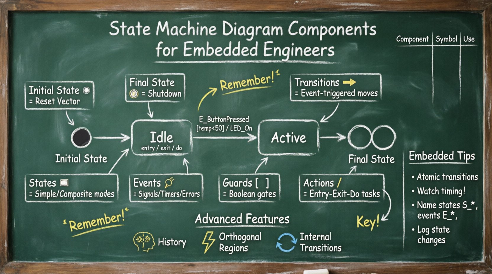
1. Initial State (Start Point) ▶️
Every state machine must begin somewhere. The initial state represents the entry point of the system. It is typically depicted as a solid filled circle. This node does not represent a condition the system stays in; it represents the moment the system initializes. Upon power-up or reset, the flow moves from the initial state to a concrete state immediately. In embedded contexts, this often maps to the reset vector in the firmware. It ensures the system does not start in an undefined or floating condition.
2. Final State (End Point) 🏁
Conversely, a final state marks the termination of a specific process or the entire system. It is drawn as a solid filled circle surrounded by a ring. In embedded systems, true termination is rare because devices usually run indefinitely (e.g., a router or a sensor node). However, final states are useful for modeling specific tasks, such as a shutdown sequence or a boot loop completion. It signals that a particular workflow has reached a successful or failed conclusion.
3. States (The Nodes) 🏠
A state represents a condition during which the system waits for an event or executes an internal action. States are drawn as rounded rectangles. They are not just passive boxes; they encapsulate behavior. There are two main categories:
- Simple States: These are atomic. The system enters, performs an action, and waits. Examples include
Idle,Running, orStandby. - Composite States: These are hierarchical. A composite state contains sub-states. This is crucial for managing complexity. For instance, a
Communicationstate might contain sub-states forConnecting,Transmitting, andReceiving.
4. Transitions (The Arrows) ➡️
A transition defines how the system moves from one state to another. It is represented by a directed arrow. A transition is triggered by an event. It may have a guard condition and an action. In embedded engineering, transitions are the critical path of execution. A transition might be triggered by a timer interrupt, a button press, or a sensor threshold crossing.
5. Events (The Triggers) 🔔
Events are the catalysts for change. They do not change the state themselves; they trigger the transition. Common events in embedded systems include:
- Signals: Asynchronous inputs like GPIO interrupts.
- Timers: Expiration of a counter or timeout period.
- Completion: A previous action finishing its execution.
- Errors: Hardware faults or communication failures.
6. Guard Conditions (The Gates) 🚧
A guard condition is a boolean expression that must evaluate to true for the transition to occur. It is placed inside square brackets on the transition arrow, e.g., [temperature > 50]. Guards allow the same event to trigger different paths depending on the data. This is essential for decision-making logic without cluttering the state machine with nested code blocks. If the condition is false, the system remains in the current state despite the event occurring.
7. Actions (The Behavior) 🏃
Actions are tasks performed during state entry, exit, or transition. They are categorized into three types:
- Entry: Executed immediately upon entering the state. Example: Initializing a GPIO pin.
- Exit: Executed immediately upon leaving the state. Example: Disabling an interrupt.
- Do: Executed continuously while the state is active. Example: Polling a sensor or running a control loop.
Advanced Diagram Features 🚀
Simple state machines are often insufficient for complex embedded logic. UML allows for advanced constructs that map directly to high-level firmware architectures.
1. History States (The Memory) 🧠
A history state allows a composite state to remember its previous condition. When a system re-enters a composite state after leaving it, the history state determines which sub-state to resume. There are two types:
- Deep History: Returns to the last active sub-state deep within the hierarchy.
- Shallow History: Returns to the last active top-level sub-state.
This is vital for systems that need to pause and resume operations without losing context. For example, a device might sleep and wake up; upon waking, it should return to the exact operation it was performing before sleeping.
2. Orthogonal Regions (Parallelism) ⚡
p>Not all parts of an embedded system change state at the same time. Orthogonal regions allow a state to be divided into independent sub-states that run concurrently. Visually, this is represented by a dashed line splitting a state. For instance, a Connected state might have an orthogonal region for Network and another for Display. Both can change states independently while the parent state remains active. This models multi-threaded or interrupt-driven behavior accurately.
3. Internal Transitions (Self-Loops) 🔄
An internal transition occurs when an event is handled but the state does not change. This is different from a self-loop transition where you leave and re-enter. Internal transitions are efficient for handling events that require processing but do not alter the mode of operation. For example, logging a message or toggling an LED while remaining in the Active state.
Implementation Considerations for Embedded Hardware 💾
Translating a diagram into code requires specific attention to hardware constraints. The model is abstract; the implementation is physical.
1. Interrupt Latency and State Consistency
In hardware, events often arrive via interrupts. The state machine must be designed to handle these asynchronously. If a state transition involves multiple steps, the system must ensure atomicity to avoid race conditions. For example, if transitioning from Idle to Processing involves enabling an interrupt and writing a register, both must complete before the state is considered fully Processing.
2. Memory Footprint
Composite states and orthogonal regions can increase memory usage if not implemented efficiently. Using a switch-case structure for simple states is memory-efficient. However, hierarchical states might require a stack to track the history. Engineers must balance the complexity of the model against the available RAM and Flash space of the microcontroller.
3. Timing Constraints
Timers are a common event source. A state machine might rely on a watchdog timer to detect a hang. If a transition takes too long, the system might reset. Designers must ensure that the Do action of any state completes within the expected timeout window. Complex logic inside a state can lead to missed deadlines.
Common Pitfalls and Best Practices ✅
Even with a good model, implementation errors occur. Here are common issues and how to avoid them.
1. State Explosion
As features are added, the number of states can grow exponentially. A diagram with hundreds of states becomes unreadable. To prevent this:
- Use composite states to group related logic.
- Avoid creating states for every possible combination of flags.
- Use guard conditions to handle variations instead of creating new states.
2. Deadlocks
A deadlock occurs when the system enters a state where no transitions are possible. This often happens if a guard condition is never met. Always ensure there is a path out of every state, or a specific error state that handles the deadlock condition gracefully.
3. Naming Conventions
Clear names are critical for collaboration. Use consistent naming for states and events. For example, prefix events with E_ (e.g., E_ButtonPressed) and states with S_ (e.g., S_Idle). This makes the code and the diagram easier to map. Ambiguous names like State1 or Action1 lead to confusion during maintenance.
4. Debugging Visibility
When the system fails, the state machine is the first place to look. Ensure the code tracks the current state explicitly. Logging the transition from State A to State B is more valuable than logging a generic error message. This allows engineers to reconstruct the sequence of events that led to a failure.
Visualizing Logic for Collaboration 🤝
State machines are not just for the coder. They serve as a communication tool between hardware engineers, software engineers, and product managers. A clear diagram bridges the gap between requirements and implementation.
- Hardware Team: Needs to know when the software expects specific pin states or interrupt configurations.
- Software Team: Needs to know the exact sequence of operations required for a feature.
- QA Team: Uses the diagram to write test cases that cover every state and transition path.
By sharing the model early, teams can identify logical gaps before writing a single line of code. This reduces the cost of fixing bugs later in the development cycle.
Component Summary Table 📊
The following table summarizes the key components for quick reference.
| Component | Symbol | Function | Embedded Context |
|---|---|---|---|
| Initial State | ● | Start of flow | Reset Vector Entry |
| Final State | ⦿ | End of flow | Shutdown Sequence |
| State | ⬜ | Condition holding | Firmware Mode (e.g., Sleep) |
| Transition | ➡️ | Change condition | Event Handler Trigger |
| Guard | [ ] | Condition check | Threshold Validation |
| Action | / | Execute logic | GPIO Toggle / ISR |
Transition Triggers Reference ⚡
Understanding what triggers a move is as important as the move itself. Below is a list of common triggers found in embedded applications.
- Event-Driven: Button press, sensor threshold, network packet arrival.
- Time-Driven: Timer expiration, heartbeat timeout, periodic poll.
- Data-Driven: Buffer full, command received, checksum error.
- System-Driven: Power loss, watchdog reset, low battery warning.
Each trigger type requires different handling in the code. Event-driven logic usually relies on interrupt service routines. Time-driven logic often uses system ticks or hardware timers. Data-driven logic checks input buffers. Mapping these triggers to the diagram ensures the code structure matches the design intent.
Final Thoughts on Modeling ⏳
State machine diagrams are a tool for clarity, not a restriction. They provide a roadmap for the firmware’s journey. By breaking down the system into discrete states and well-defined transitions, engineers can build robust systems that handle edge cases gracefully. The effort spent designing the diagram upfront saves significant time during debugging and feature expansion. For embedded engineers, mastering the components of a state machine is less about syntax and more about structuring logic to match the physical reality of the hardware. This approach leads to code that is easier to read, test, and maintain. 🛡️
When you next face a complex behavior in your project, sketch the states. Define the events. Check the guards. Let the diagram guide the implementation. This discipline separates functional prototypes from production-ready embedded products.
