


In the domain of embedded systems and autonomous robotics, managing complex behavior requires more than simple conditional statements. A well-defined State Machine Diagram offers a structured approach to modeling the dynamic behavior of a system. This guide presents a comprehensive case study focusing on the design of control logic for an autonomous drone using UML State Machine principles. We will explore how to define states, manage transitions, handle events, and ensure robust operation under real-world constraints.
Understanding State Machine Diagrams in UML 📐
A State Machine Diagram, often referred to as a State Chart Diagram in UML 2.0, represents the discrete states of an object or system and the transitions between those states. Unlike a static class diagram, this model captures the temporal behavior of the system. It is particularly useful for reactive systems where the output depends on the current state and incoming events.
Key components include:
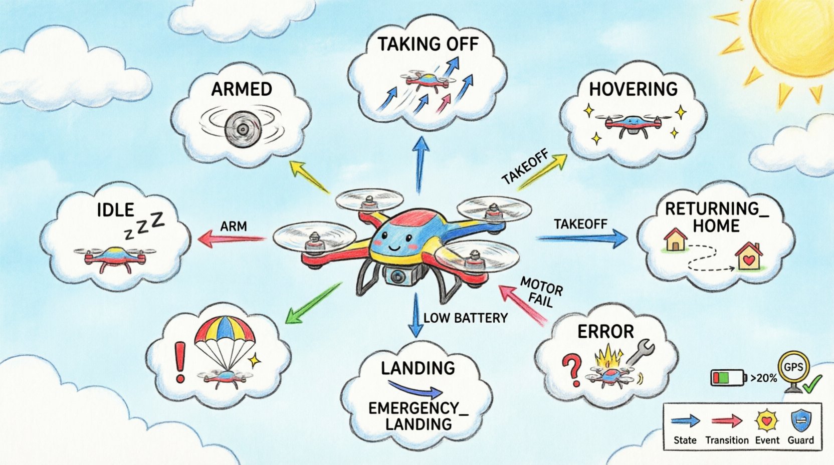
- State: A condition or situation during the life of an object during which it satisfies some condition, performs some activity, or waits for some event.
- Transition: A relationship between two states indicating that objects in the first state will move to the second state when a specific event occurs and certain conditions are met.
- Event: A significant occurrence, such as a signal receipt, a time elapse, or an exception, that triggers a transition.
- Guard Condition: A Boolean expression that must be true for the transition to occur.
- Action: A computation or activity performed upon entering, exiting, or during a transition.
Using this notation allows engineers to visualize the control flow without getting lost in code syntax. It serves as a blueprint for implementation, ensuring that all possible system behaviors are accounted for before writing a single line of executable code.
The Case Study: Autonomous Delivery Drone 🚁
Consider a quadcopter drone designed for last-mile package delivery in an urban environment. This system must operate autonomously but requires human oversight for specific critical events. The drone is equipped with GPS, battery management systems, obstacle avoidance sensors, and a communication module. The control logic must handle normal operations, navigation, and various failure modes.
The design challenge involves ensuring the drone does not attempt to take off with low battery, does not lose connection without returning home, and safely lands in an emergency. A linear script would be difficult to maintain and prone to race conditions. A State Machine provides a clear hierarchy of operations.
Defining the Core States ⚙️
The first step in the design process is identifying the distinct modes of operation. For this drone, we define the following primary states. Each state represents a specific phase of the mission.
- IDLE: The drone is powered on but not armed. It waits for a command to begin the mission.
- ARMED: The motors are spinning, and the drone is ready for takeoff. It is not yet in the air.
- TAKING_OFF: The drone is ascending from the ground to a stable hover altitude.
- HOVERING: The drone is stationary in the air, maintaining position.
- NAVIGATING: The drone is actively moving between waypoints to deliver the payload.
- RETURNING_HOME: The drone is flying back to the launch location due to low battery or signal loss.
- LANDING: The drone is descending from the air to the ground.
- EMERGENCY_LANDING: An immediate, forced descent due to critical failure (e.g., motor failure).
- ERROR: A catch-all state for unhandled faults or system resets.
Notice that states like IDLE and ERROR are terminal or quasi-terminal. Once the system enters ERROR, it cannot proceed to NAVIGATING without a manual reset. This prevents the drone from attempting to fly while in a fault condition.
Transition Logic and Event Triggers 📡
Transitions define how the system moves between the states listed above. These movements are triggered by events such as user input, sensor readings, or internal timers. The table below outlines the critical transitions required for the control logic.
| Event | Source State | Target State | Guard Condition |
|---|---|---|---|
| ARM_COMMAND | IDLE | ARMED | Battery > 20% |
| TAKEOFF_COMPLETE | ARMED | TAKING_OFF | Altitude Sensor Active |
| REACH_HOVER | TAKING_OFF | HOVERING | Altitude = 1.5m |
| START_MISSION | HOVERING | NAVIGATING | GPS Lock = True |
| BATTERY_LOW | NAVIGATING | RETURNING_HOME | Battery < 30% |
| SIGNAL_LOSS | NAVIGATING | RETURNING_HOME | Time > 5s without signal |
| REACH_HOME | RETURNING_HOME | LANDING | Distance = 0m |
| TOUCH_DOWN | LANDING | IDLE | Altitude = 0m |
| MOTOR_FAILURE | Any | EMERGENCY_LANDING | Current < 0A |
Observe that the MOTOR_FAILURE event has a source state of Any. This is known as an orthogonal transition or an interrupt. Regardless of whether the drone is IDLE or NAVIGATING, a critical motor failure forces an immediate state change to EMERGENCY_LANDING. This ensures safety is prioritized over mission continuity.
Guard Conditions and Actions 🛑
Transitions are not always unconditional. Guard conditions act as safety checks. For example, a user cannot initiate a takeoff sequence if the battery is critically low. The guard condition Battery > 20% prevents the transition from IDLE to ARMED.
Additionally, transitions often trigger actions. These actions are executed when the transition occurs or while in a specific state.
- Entry Action: Code executed immediately upon entering a state. For the TAKING_OFF state, an entry action might be to set motor thrust to 60% and initialize the altitude PID controller.
- Exit Action: Code executed immediately upon leaving a state. When exiting HOVERING, the system might stop the waypoint follower to prevent conflicting commands.
- Do Activity: Code executed continuously while in a state. In the NAVIGATING state, a Do activity involves continuously reading GPS data and adjusting motor speeds to maintain the flight path.
Consider the RETURNING_HOME state. Upon entry, the drone must calculate the vector back to the home point. Upon exit, it must clear the return vector. This ensures that if the drone switches back to NAVIGATING (perhaps because the user regained control), the return logic does not interfere with the mission logic.
Hierarchical State Design (Composite States) 🏗️
Flat state machines can become unwieldy as complexity grows. Hierarchical State Machines allow states to contain sub-states. This is particularly useful for the NAVIGATING state. Navigation is not a single action; it is a collection of behaviors.
We can define NAVIGATING as a composite state with the following internal sub-states:
- WAYPOINT_FOLLOWING: The standard mode where the drone moves between points.
- COLLISION_AVOIDANCE: A state entered when an obstacle is detected.
- STABILIZATION: A low-level state managing motor balance during wind gusts.
Transitions between these sub-states occur without leaving the parent NAVIGATING state. For instance, if an obstacle is detected, the system transitions from WAYPOINT_FOLLOWING to COLLISION_AVOIDANCE. The parent state remains active, preserving the overall mission context. Once the obstacle is cleared, the system returns to WAYPOINT_FOLLOWING.
This structure reduces redundancy. Common actions for navigation, such as updating telemetry logs, can be defined at the parent level rather than repeating them in every sub-state. It also improves clarity by grouping related behaviors together visually.
Implementation Considerations for Embedded Systems 💻
Translating a State Machine Diagram into executable code requires attention to the constraints of the embedded hardware. The drone flight controller typically runs on a microcontroller with limited RAM and CPU cycles.
- Memory Efficiency: Avoid storing the entire state history. Only track the current state. Using an enumeration or integer to represent the state minimizes memory usage.
- Real-Time Responsiveness: Transitions must happen deterministically. If the EMERGENCY_LANDING event is triggered, the code must not wait for a long-running task to finish. Interrupts should be handled outside the main state loop or with high priority.
- State Consistency: Ensure that no state has undefined behavior. Every possible event must have a defined transition. If an unexpected event occurs, the system should transition to an ERROR state rather than crashing or hanging.
- Logging: Implement a state logging mechanism. When a transition occurs, write the timestamp, source state, target state, and event to non-volatile memory. This is crucial for post-flight analysis.
For example, when implementing the TAKING_OFF state, the code should not block. It should use a non-blocking timer to monitor altitude. If the altitude does not increase within a set time, it should trigger a timeout event and transition to ERROR.
Testing and Verification Strategies 🧪
Before deploying the drone, the state machine logic must be verified. Simulation is the most cost-effective method. By creating a software simulator that mimics the sensor inputs, engineers can test every possible path through the state diagram without risking hardware.
Key testing activities include:
- Boundary Testing: Test transitions that rely on specific thresholds. For example, verify that the transition to RETURNING_HOME happens exactly when the battery drops below 30%, and not at 29% or 31%.
- Path Coverage: Ensure every transition line in the diagram is traversed at least once during testing. This confirms that the logic for every event is functional.
- Interrupt Testing: Simulate events that should interrupt the current state. Verify that the system correctly exits NAVIGATING and enters EMERGENCY_LANDING even if a long calculation is running.
- Reset Testing: Verify that the system can recover from the ERROR state. Can it be manually reset to IDLE without a physical power cycle?
Model checking tools can also be used. These tools mathematically verify that the state machine does not contain deadlocks (states where no transitions are possible) or unreachable states (states that cannot be entered from the initial state).
Common Pitfalls to Avoid ⚠️
Even with a well-designed diagram, implementation errors can occur. Below are common issues observed in drone control systems.
- Missing Transitions: It is easy to forget a transition for a specific event. For example, what happens if the battery dies while in EMERGENCY_LANDING? The drone must still execute a controlled descent or free-fall protection logic.
- State Confusion: Using too many similar states. For instance, having both HOVERING and WAITING can be confusing. Combine them if their behaviors are identical.
- Blocking Operations: Do not use blocking code inside a state action. If an action waits for a sensor, the entire state machine freezes. Use asynchronous callbacks or flags instead.
- Unintended Loops: Ensure there are no infinite loops of states that consume CPU cycles without performing useful work. For example, a loop between ERROR and IDLE without a reset command will cause a crash.
Summary of Benefits 🏆
Designing a drone control system using a State Machine Diagram provides significant advantages over traditional procedural coding. It enforces a clear separation of concerns, making the code easier to read and debug. By explicitly defining states and transitions, developers ensure that the system behaves predictably in all scenarios.
This approach facilitates collaboration between hardware and software teams. The diagram serves as a shared language. Hardware engineers can see exactly when sensors are polled, and software engineers can see when actuators are commanded. It also simplifies onboarding new team members, as the logic is visualized rather than hidden in complex code structures.
Ultimately, the investment in designing a robust state machine pays off in reliability. An autonomous drone is a complex system, and managing its behavior requires a disciplined methodology. By adhering to UML standards and carefully planning transitions, guards, and actions, engineers can build systems that are safe, maintainable, and efficient. This case study demonstrates that while the logic is complex, the structure provides clarity and control over the autonomous behavior.
