


Robotic systems operate in dynamic, unpredictable environments. A single failure in sensor input or motor execution can lead to catastrophic outcomes. To mitigate these risks, engineers rely on structured design methodologies. The State Machine Diagram (SMD) is a fundamental tool within the Unified Modeling Language (UML) that defines behavior through distinct states and transitions. When applied to error handling, this diagram becomes the backbone of fault tolerance.
This guide explores how to architect error-handling logic using state machines. We examine the lifecycle of an error, the design of recovery states, and the critical nature of transition guards. By integrating these patterns, systems achieve higher reliability without compromising operational efficiency.
🧩 Understanding UML State Machines in Robotics
A state machine is a model of behavior. It consists of a finite number of states, transitions between those states, and actions associated with entering, exiting, or completing transitions. In robotics, these states represent the operational mode of the machine.
Key components include:
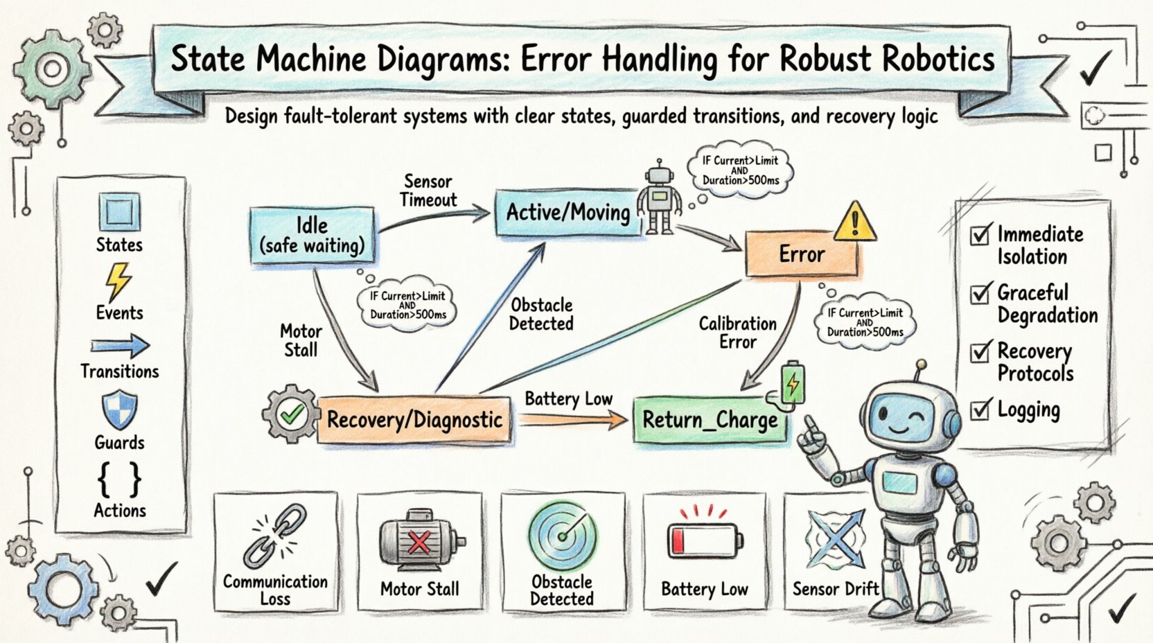
- States: Conditions under which the system remains until an event occurs (e.g., Idle, Moving, Error).
- Events: Triggers that cause a transition (e.g., Sensor Timeout, Command Received).
- Transitions: The path taken from one state to another based on an event.
- Guards: Boolean conditions that must be true for a transition to occur.
- Actions: Code or logic executed during a transition or state entry/exit.
Unlike simple if-else logic, state machines provide a clear visual representation of system flow. This visibility is crucial for debugging complex robotic behaviors where asynchronous events are common.
⚠️ The Critical Role of Error Handling
Robots often operate near physical limits. Mechanical wear, electrical noise, or environmental changes can introduce faults. Ignoring these faults leads to cascading failures. An error-handling strategy must be proactive, not reactive.
Effective error handling in state machines involves:
- Immediate Isolation: Preventing the system from entering unsafe states.
- Graceful Degradation: Continuing operations at a reduced capacity if possible.
- Recovery Protocols: Specific steps to return to a functional state.
- Logging: Recording the sequence of events leading to the error.
When designing the diagram, every active state must have a defined path to an error state. There should be no “dead ends” where a system hangs indefinitely.
🛡️ Designing States for Error Recovery
The structure of the state machine dictates how errors are perceived and resolved. A flat hierarchy can become unmanageable as complexity grows. A hierarchical structure allows for shared error handling logic.
1. The Error State
The Error state is not merely a stop sign; it is an active state where the system waits for intervention or automatic recovery. It should be distinct from the Idle state.
- Entry Action: Trigger safety brakes, cut power to actuators, or log the fault code.
- Exit Action: Reset sensors, clear buffers, or verify hardware integrity.
- Internal Transition: Handle non-fatal notifications without leaving the state.
2. The Recovery State
Before returning to normal operation, a system may pass through a Recovery or Diagnostic state. This ensures that the root cause is addressed.
- Verification: Run self-tests to confirm sensors are functional.
- Reset: Re-initialize communication protocols.
- Confirmation: Require operator acknowledgment before resuming movement.
3. The Idle State
The Idle state represents a safe, waiting condition. It is the default state when no active task is assigned. Transitions from Error often lead to Idle rather than directly to Active.
This prevents the robot from attempting a task immediately after a fault, which could exacerbate the issue.
🔄 Transition Logic and Guards
Transitions are the decision points. A transition from Active to Error should only occur if specific conditions are met. These conditions are defined by guards.
Defining Guards
A guard ensures that a transition is valid. For example, a motor stall error should only trigger an error transition if the stall duration exceeds a threshold.
IF (Motor_Current > Limit) AND (Duration > 500ms) THEN Transition to Error
Without guards, transient spikes in data could trigger unnecessary state changes, causing the system to oscillate between states.
Handling Asynchronous Events
Robotic systems handle asynchronous inputs. A state machine must queue events if they arrive while the system is processing a long-duration action.
- Event Queue: Store incoming events until the current action completes.
- Priority Handling: Critical errors (e.g., collision detection) bypass the queue.
- Timeouts: If an action takes too long, trigger a transition to a timeout state.
📊 Common Robotics Error Scenarios
Different types of robots face unique challenges. The following table outlines common scenarios and their corresponding state machine responses.
| Scenario | Trigger Event | Target State | Recovery Action |
|---|---|---|---|
| Communication Loss | Link_Timeout |
Com_Error | Attempt reconnection; switch to local control mode. |
| Motor Stall | Current_Exceeded |
Motion_Error | Cut power, wait for cooldown, verify mechanical binding. |
| Obstacle Detected | Proximity_Alert |
Pause | Stop motion, update map, plan new path. |
| Battery Low | Voltage_Critical |
Return_Charge | Stop task, navigate to dock, initiate charging protocol. |
| Sensor Calibration Drift | Calibration_Error |
Diagnostic | Run calibration routine, verify accuracy, resume if passed. |
Each row in the table represents a specific branch in the state diagram. The Target State must be clearly defined to avoid ambiguity.
🏗️ Hierarchical States and Submachines
As systems grow, a flat list of states becomes difficult to manage. Hierarchical state machines allow for substates.
Grouping Similar Behaviors
If a robot has multiple movement modes (e.g., Walk, Drive, Crawl), these can be grouped under a parent state called Motion.
- Parent State: Motion
- Child States: Walk, Drive, Crawl
- Error Handling: An error occurring in Walk can transition to a shared Error state without defining a new path for every child.
History States
A history state preserves the last active substate before an interruption. This is useful when a system is paused and resumed.
- Deep History: Returns to the specific substate active when interrupted.
- Shallow History: Returns to the last substate within the parent.
For example, if a robot is in Drive and receives a Pause command, it goes to Paused. Upon receiving Resume, it returns to Drive rather than defaulting to Idle.
⚙️ Implementation Considerations
Designing the diagram is only the first step. Implementation requires careful attention to timing and resource management.
State Timing
Some states require time delays. A Cooldown state might wait for 10 seconds before allowing a retry. This must be managed without freezing the main control loop.
- Non-Blocking Timers: Use timers that do not halt the processor.
- Tick Counters: Increment a counter on every main loop cycle.
Resource Cleanup
When leaving a state, resources must be released. This includes file handles, memory buffers, and hardware locks.
- Exit Actions: Define specific cleanup tasks for every state.
- Initialization: Ensure resources are ready upon entry.
Debugging and Visibility
During development, it is essential to know the current state. State machines should expose their status via telemetry.
- State Logging: Write state changes to a log file.
- Visual Indicators: Use LEDs or UI elements to show the active state.
- Traceability: Map log entries to specific state transitions.
🧪 Testing and Verification
Testing state machines requires covering all paths. This includes normal operation, edge cases, and failure modes.
State Coverage
Every state must be visited during testing. Ensure that entry and exit actions are triggered correctly.
- Unit Testing: Test individual transitions in isolation.
- Integration Testing: Test the full system with simulated inputs.
Stress Testing
Push the system to its limits. Send rapid-fire error events to check for race conditions.
- Flood Testing: Send more events than the system can handle.
- Timing Attacks: Change event timing to catch logic errors.
Recovery Validation
Verify that the system actually recovers. Does it return to the expected state? Are all safety checks passed?
- Replay Logs: Replay recorded error sequences to verify consistency.
- Hardware-in-the-Loop: Test with physical hardware to catch timing issues.
📋 Best Practices Summary
To ensure robustness, adhere to the following guidelines when designing error handling in state machines.
| Practice | Description |
|---|---|
| Explicit Error States | Do not hide errors within normal states. Isolate them clearly. |
| Fail-Safe Defaults | Ensure the system defaults to a safe state on power loss. |
| Timeout Guards | Always include timeouts to prevent infinite waiting. |
| State Logging | Maintain a record of all state changes for post-mortem analysis. |
| Minimal Transitions | Reduce complexity by grouping states hierarchically. |
| Clear Naming | Use descriptive names for states and events to improve readability. |
🔍 Conclusion
Designing error handling for robotics systems requires a disciplined approach. State Machine Diagrams provide the necessary structure to manage complexity and ensure safety. By defining clear states, robust transitions, and comprehensive recovery logic, engineers can build systems that withstand the unpredictability of the real world.
The focus remains on reliability. Every transition must be deliberate, and every error must be accounted for. Through careful design and rigorous testing, robotics systems can achieve the level of performance and safety required for critical applications.
Adopting these principles leads to machines that are not just functional, but resilient. They recover from faults gracefully, maintain safety protocols, and continue to deliver value even under adverse conditions.
