


Robotics programming involves managing complex interactions between sensors, actuators, and decision-making logic. When a robot operates autonomously, it must handle various conditions without human intervention. A finite state machine (FSM) provides a structured method to model this behavior. This guide covers UML state machine diagrams specifically for robotics contexts, helping you visualize logic without relying on specific software tools.
🧠 Why Use State Machines in Robotics?
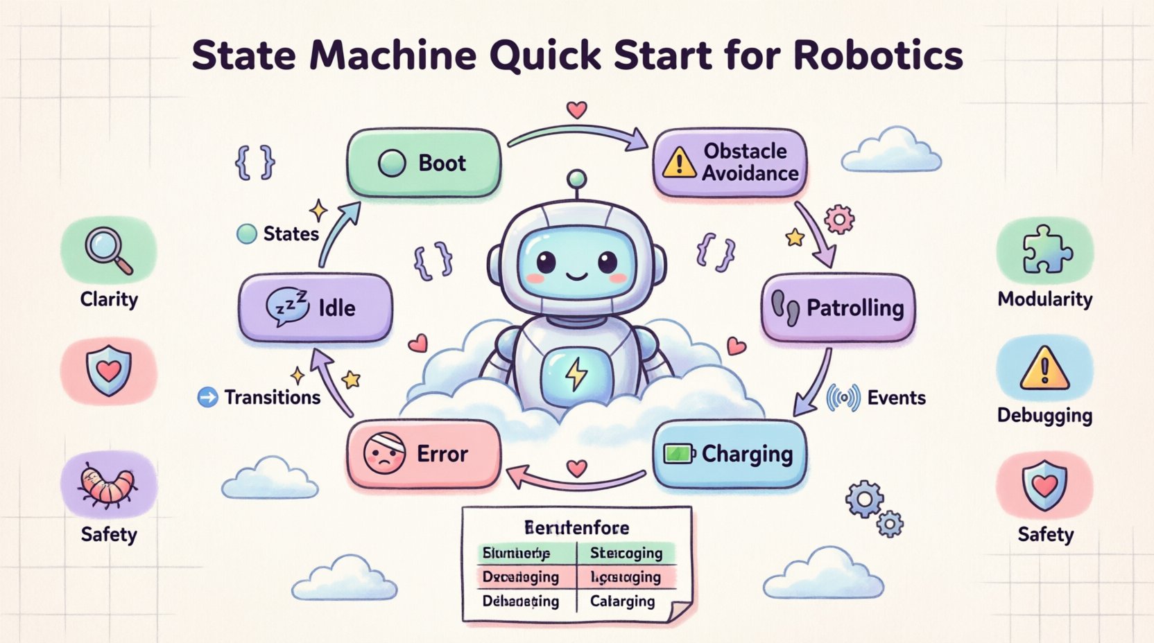
Robot systems often operate in environments where inputs change unpredictably. A linear script cannot easily handle scenarios where the robot must pause, wait for a sensor, resume, or stop due to an error. State machines break down behavior into discrete states. In any given moment, the robot is in one specific state, and transitions occur when specific events happen.
Using diagrams to map this logic offers several benefits:
- Clarity: Visual representations are easier to review than lines of code.
- Modularity: Complex behaviors can be nested within parent states.
- Debugging: It is easier to trace the flow of control when the logic is visualized.
- Safety: Critical states like “Emergency Stop” are clearly defined and hard to miss.
📐 Core Components of a State Machine Diagram
To build a diagram, you must understand the fundamental building blocks. These elements form the vocabulary of your design.
1. States (🟦)
A state represents a condition during which the robot performs a specific task or waits for a condition. States are usually drawn as rounded rectangles.
- Initial State: The starting point, often a small filled circle.
- Final State: The end point, usually a double circle.
- Simple State: A single condition (e.g., Idle, Charging).
- Composite State: A state containing sub-states (e.g., Navigation containing FollowLine and AvoidObstacle).
2. Transitions (➡️)
A transition defines how the system moves from one state to another. It is represented by a line with an arrowhead.
- Trigger: The event that causes the move (e.g., Button Pressed, Obstacle Detected).
- Guard Condition: A boolean expression that must be true for the transition to occur (e.g., [Battery > 20%]).
- Action: Code executed during the transition (e.g., Log Error, Reset Sensor).
3. Events and Signals (📡)
Events are occurrences that trigger transitions. In robotics, these often come from:
- Sensor inputs (LiDAR, Cameras, Touch).
- Internal timers (Timeouts).
- External commands (User interface, Remote control).
🛠️ Designing a Robot Controller: Step-by-Step
Let us walk through designing a state machine for an autonomous mobile robot tasked with patrolling a warehouse. We will not use any drawing software; we will define the logic conceptually and then structure it.
Step 1: Define the Entry Point
Every program starts somewhere. For a robot, this is often the Boot Sequence. During this state, the system initializes hardware, checks connections, and loads configuration files.
Step 2: Identify Primary Operational States
Once booted, what are the main modes? Consider the following:
- Idle: Robot is stationary, waiting for a command.
- Patrolling: Robot is moving along a predefined path.
- Obstacle Avoidance: Robot detects an object and maneuvers around it.
- Charging: Robot returns to a dock to recharge.
- Error: System fault detected; robot stops.
Step 3: Map the Transitions
Connect the states based on logical flow. For example:
- From Idle: Transition to Patrolling when Start Command is received.
- From Patrolling: Transition to Obstacle Avoidance when Proximity Sensor triggers.
- From Obstacle Avoidance: Transition back to Patrolling when Path Clear.
- From Any State: Transition to Charging when Battery Low.
- From Any State: Transition to Error when System Fault.
📊 State Transition Table
A table can supplement a diagram to define logic precisely. This is often easier to read than a complex visual diagram for simple systems.
| Current State | Event / Condition | Next State | Actions |
|---|---|---|---|
| Idle | Start Command | Patrolling | Initialize Path, Enable Motors |
| Patrolling | Obstacle Detected | Avoid Obstacle | Stop, Scan, Rotate |
| Avoid Obstacle | Path Clear | Patrolling | Resume Path |
| Patrolling | Battery < 20% | Charging | Stop, Locate Dock, Dock |
| Charging | Battery > 90% | Idle | Disconnect, Return to Start |
| Any State | Emergency Stop | Error | Cut Power to Motors, Log Event |
🔄 Handling Complex Logic with Hierarchical States
Real-world robots often have nested logic. A single state might contain multiple sub-states. This is known as Hierarchical State Machines.
Example: Navigation State
The Patrolling state can be a composite state. Inside it, you might have:
- Sub-State: Moving Forward: The robot drives straight.
- Sub-State: Turning: The robot adjusts direction.
- Sub-State: Stopping: The robot decelerates.
When the robot is in Patrolling, it is technically also in one of these sub-states. This allows you to define common behaviors for the parent state while keeping specific details in the children.
⚠️ Error Handling and Safety States
Robotics requires robust error management. You should always have a dedicated state for failures. This ensures the system does not loop indefinitely in a bad condition.
Key Safety Considerations
- Isolation: An error state should prevent execution of motion commands.
- Visibility: The state should trigger an alert (LED, Sound, Log).
- Recovery: Define if the system can recover automatically or requires human intervention.
- Timeouts: If a transition takes too long, force a transition to an error state.
Example: Motor Timeout
If the robot attempts to move but the encoder does not register movement for 5 seconds:
- Trigger: Timeout Event.
- Transition: From Patrolling to Error.
- Action: Set flag Motor Stall.
🧪 Debugging and Testing State Logic
Once the diagram is drawn, how do you verify it works? You do not need a specific IDE to test the logic on paper first.
1. Walkthrough Simulation
Take a pen and trace paths on your diagram. Pretend to be the robot. Ask:
- Can I reach every state?
- Are there states I cannot leave (deadlocks)?
- What happens if two events happen at the same time?
2. Coverage Analysis
Ensure every state has at least one incoming transition and one outgoing transition (except start and end). This prevents the robot from getting stuck.
3. Edge Case Testing
Consider scenarios not in the main flow:
- Power loss during a transition.
- Sensor noise (rapid toggling of events).
- Simultaneous high-priority events.
🚀 Common Patterns in Robotics
Several patterns appear frequently in robotic state machines. Recognizing these can speed up your design process.
The Watchdog Timer
A timer that resets only if the system is functioning correctly. If the timer expires, it forces a transition to a safe state (like Reboot).
The Fallback State
A generic state used when specific conditions are not met. For example, if a navigation algorithm fails, the robot enters a Searching for Home state rather than crashing.
Preemptive States
States that interrupt others. The Emergency Stop state is the ultimate preemptive state. It overrides Patrolling, Charging, or Idle immediately.
🛠️ Best Practices for Diagramming
Follow these guidelines to keep your diagrams maintainable and clear.
1. Keep States Atomic
Avoid making states too complex. If a state contains too much logic, break it into smaller sub-states. A state should represent what the robot is doing, not how it does it in detail.
2. Use Clear Naming
Names should be descriptive. Avoid generic names like State 1. Use Waiting for Dock instead of Waiting.
3. Limit Transitions
Too many lines crossing each other makes a diagram unreadable. If a state has too many transitions, consider grouping them or using a composite state.
4. Document Guard Conditions
Always write out the exact condition for a transition. Don’t just write “Error”; write “[Error Flag == True]”.
5. Version Control
Even though you are not using software, treat your diagrams like code. Keep versions. If you change the logic, note what changed and why.
🔄 Concurrency in Robotics
Some robots perform multiple tasks simultaneously. While basic state machines are sequential, advanced designs handle concurrency. This means the robot can be in multiple states at once.
Example: Monitoring and Moving
A robot might be Patrolling while simultaneously Monitoring Sensors. In a diagram, this is often represented by parallel regions.
- Region 1: Motion Control (Patrolling, Stopping).
- Region 2: Sensor Monitoring (Listening, Scanning).
Changes in Region 2 do not necessarily stop Region 1. This adds complexity to the diagram but is necessary for advanced autonomy.
🧩 Integration with Code
How do you turn this diagram into working software? The diagram serves as the specification.
1. Enumerations
Map each state to an enumeration in your code. This prevents typos in state names.
2. Switch/Case Statements
Use the state variable to switch between different logic blocks. This mirrors the visual structure of the diagram.
3. Event Queues
Events should be stored in a queue. The main loop processes one event at a time, triggering the appropriate transition based on the current state.
📈 Scaling Your Logic
As your robot project grows, the state machine will grow. You might need to refactor your diagram.
- Modularization: Extract common behaviors into separate state machines that can be reused across different robots.
- Abstraction: Hide low-level details. The high-level state machine should deal with Move, not Motor Speed.
- Review Cycles: Regularly review the diagram with your team to ensure it matches the current implementation.
🔧 Troubleshooting Common Issues
Even with a good diagram, implementation issues arise.
Issue: Race Conditions
If two events happen almost simultaneously, the robot might react unpredictably. Use event queuing to ensure a strict order of processing.
Issue: Infinite Loops
A state machine might loop between two states without doing work. Ensure transitions have guard conditions that eventually become true.
Issue: State Mismatch
The code might be in a different state than the diagram suggests. Add logging to the entry and exit points of every state to verify synchronization.
🎓 Summary of Key Takeaways
Designing a state machine for robotics is about clarity and control. It forces you to think about every possible condition before writing code.
- Start with a clear definition of states and events.
- Use diagrams to visualize the flow before coding.
- Handle errors explicitly with dedicated states.
- Keep states simple and atomic.
- Test the logic on paper before deployment.
- Use tables to supplement complex transitions.
By mastering the structure of state machine diagrams, you build a foundation for robust, reliable robotic systems. This approach reduces bugs and makes maintenance significantly easier for future updates.
