


Embedded systems rely heavily on deterministic behavior. When a device operates, it must respond predictably to inputs within specific conditions. State Machine Diagrams, often part of the Unified Modeling Language (UML), serve as the blueprint for this behavior. However, translating a diagram into code is where errors often hide. Logic errors in finite state machines (FSMs) can lead to system hangs, unexpected resets, or safety hazards. 🚨
This guide provides a structured approach to identifying and resolving logic errors within state machine designs. By understanding the nuances of state transitions, guard conditions, and hierarchical structures, developers can ensure their embedded software behaves as intended.
🧩 Understanding the Complexity of FSMs
A state machine defines the possible states of a system and how it moves between them. In embedded contexts, this often involves hardware interactions, timers, and external interrupts. Unlike simple procedural code, state machines maintain context. If the context is lost or corrupted, the logic fails.
Common scenarios where FSMs are critical include:
- Communication protocols (e.g., UART, SPI, I2C state handling)
- User interface navigation (e.g., button presses, screen transitions)
- Power management modes (e.g., sleep, active, standby)
- Motor control sequences (e.g., start, run, stop, error)
When troubleshooting, it is vital to distinguish between implementation bugs and design flaws. A design flaw exists when the diagram itself does not cover a valid scenario. An implementation bug occurs when the code does not follow the diagram.
⚠️ Common Logic Errors in Embedded State Machines
Debugging state logic requires a keen eye for detail. Certain patterns of errors recur frequently. Recognizing these patterns accelerates the resolution process.
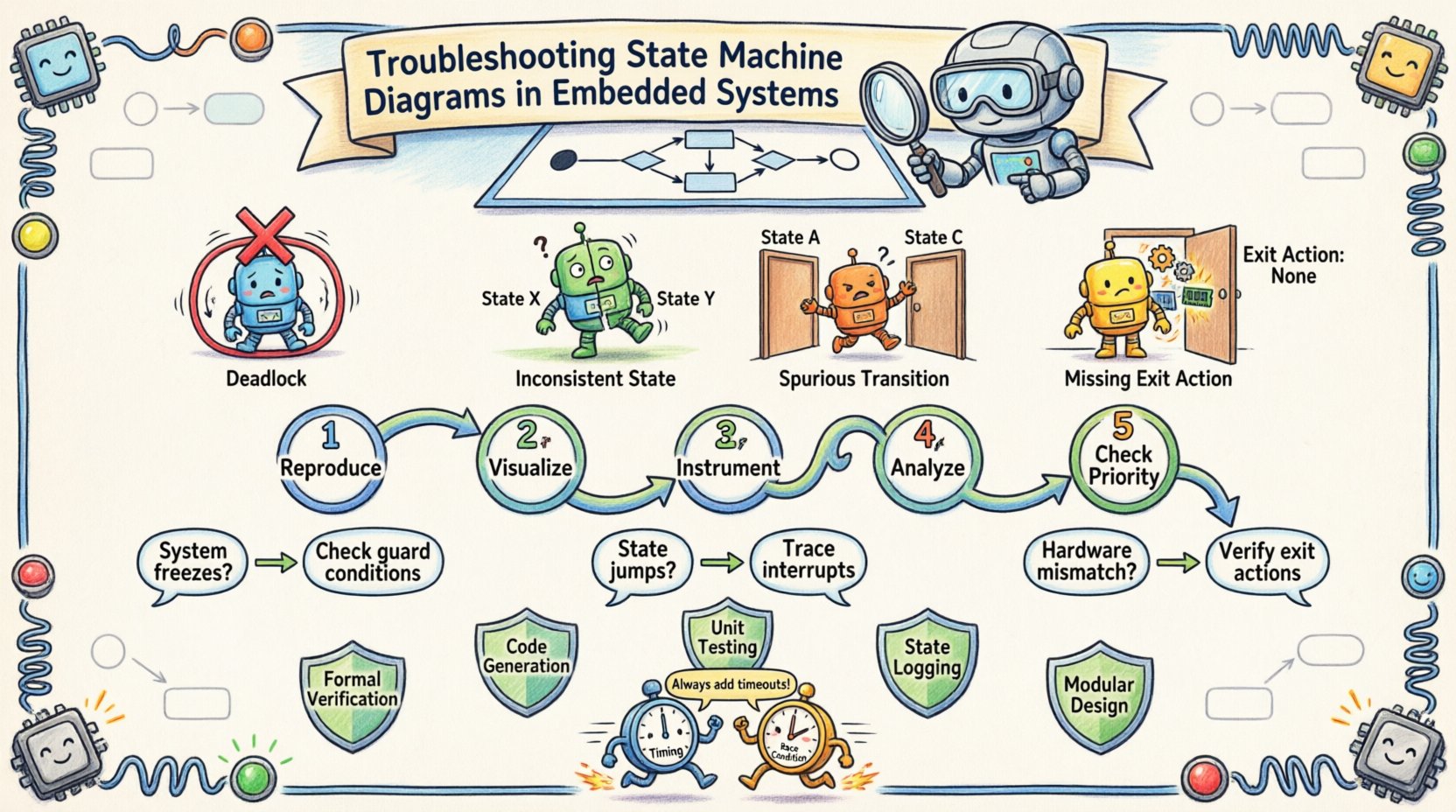
1. The Deadlock Scenario
A deadlock occurs when the system enters a state where no transitions are possible, yet the system is not in a terminal or error state. The processor sits idle, waiting for an event that will never arrive. This is often caused by:
- Missing default transitions (self-loops) for unhandled events.
- Guard conditions that are always false.
- Logic that clears an event flag before the state machine checks it.
2. Spurious Transitions
Spurious transitions happen when the system moves to a state it should not. This usually stems from:
- Multiple events triggering the same transition path without proper exclusion.
- Incorrect handling of event queues where an old event triggers a new state.
- Concurrent states that are not properly synchronized.
3. Inconsistent States
This occurs when the internal variables do not match the current state of the machine. For example, a motor might be in the “Running” state in the diagram, but the hardware register indicates “Stopped”. This desynchronization creates confusion for subsequent transitions.
4. The Missing Exit Action
In complex machines, exiting a state often requires cleanup. If the exit action is omitted in the code but present in the design, resources (like memory or locks) remain allocated. Over time, this leads to resource exhaustion.
📊 Error Types vs. Symptoms
Refer to the table below to map observed behavior to potential root causes.
| Observed Symptom | Potential Root Cause | Diagnostic Focus |
|---|---|---|
| System freezes at specific input | Deadlock or missing transition | Check event queue and guard conditions |
| State jumps unexpectedly | Spurious transition or race condition | Trace interrupt timing and event flags |
| Hardware does not match state | Missing exit action or update | Verify hardware register writes on exit |
| Intermittent failures under load | Timing or race condition | Analyze stack usage and timer intervals |
| System boots to wrong state | Initialization error | Check reset handler and default state |
🔍 Step-by-Step Diagnostic Workflow
When logic errors appear, a systematic approach prevents wasted time. Do not guess; measure.
1. Reproduce the Issue
Ensure the error is reproducible. If the issue is intermittent, attempt to isolate the conditions. Document the sequence of events leading to the failure. A state machine is deterministic; if you trigger the same sequence, you should get the same result.
2. Visualize the Flow
Open the UML diagram. Trace the path visually. Highlight the starting state and the target state. Look for gaps in the diagram. Does the diagram account for every possible input in every state? If an input is not drawn, the code might be ignoring it or handling it incorrectly.
3. Instrument the Code
Add logging to key transition points. This does not require expensive tools. Simple print statements or toggling GPIO pins can reveal the state of the system at runtime. Log the:
- Current State ID
- Triggering Event
- Guard Condition Evaluation
- Target State
4. Analyze the State Entry and Exit
Verify that entry and exit actions are firing. Often, the transition happens, but the side effects (like setting a pin high) do not. Ensure the state machine logic updates the hardware immediately upon entry.
5. Check Event Prioritization
If multiple events occur simultaneously, which one takes precedence? The code must define a clear priority. If the code prioritizes Event A but the design expects Event B, the logic will drift.
🧠 Deep Dive: Guard Conditions and Trigger Events
Guard conditions are boolean expressions that must be true for a transition to occur. They are the logic gates of the state machine. Errors here are subtle because the transition path exists, but the condition prevents it.
Common Guard Condition Pitfalls
- Variable Scope: The variable used in the guard condition might not be updated when expected. If a flag is set in an interrupt but read in the main loop, timing issues arise.
- Logic Negation: A simple typo, such as using
!=instead of==, can invert the entire logic flow. - Side Effects: Guard conditions should generally be read-only. If a guard condition modifies a global variable, it creates hidden state changes that are hard to track.
Event Handling Nuances
Events are the triggers. They can be:
- Signals: Asynchronous inputs (e.g., button press).
- Timers: Periodic inputs (e.g., watchdog tick).
- Errors: Exceptional inputs (e.g., CRC mismatch).
Ensure the event source is cleared after processing. If an event flag remains set, the state machine might process the same event twice, causing a spurious transition.
🏗️ Managing Hierarchical States and Inheritance
Complex systems use hierarchical states to reduce diagram clutter. A parent state contains child states. Transitions can occur at the parent level, affecting all children.
Issues with Hierarchy
When debugging hierarchical states, confusion often arises regarding where the state actually resides.
- Implicit Transitions: Moving from a child state to a sibling state often requires exiting the parent. Ensure the exit actions of the parent are executed correctly.
- Default Entry Points: When a parent state is entered, which child state is active? If the default child is not defined, the system may remain in an undefined state.
- Local vs. Global Transitions: A transition defined on a child state might be triggered by an event handled by the parent. Understand the scope of the event.
Best Practices for Hierarchy
- Minimize nesting depth. Deep hierarchies are difficult to trace.
- Use explicit default states for all composite states.
- Document the behavior of parent exit actions clearly.
⏱️ Timing and Race Conditions
Embedded systems operate in real-time. State machines are not immune to timing issues. Race conditions occur when the outcome depends on the relative timing of events.
Interrupt vs. Main Loop
Often, state events are generated in an Interrupt Service Routine (ISR) but processed in the main loop. If the main loop is slow, events can accumulate. If the ISR clears a flag before the main loop checks it, data is lost.
Debouncing Inputs
Physical buttons bounce. If the state machine interprets a single press as multiple presses, it will traverse the state diagram incorrectly. Implement debouncing logic within the state machine (e.g., a “Wait” state) rather than relying solely on hardware.
Timeouts
Every state that waits for an external input should have a timeout. If an expected event does not arrive within a specified duration, the system should transition to an error or recovery state. This prevents the deadlock scenario mentioned earlier.
🛡️ Prevention Strategies for Robust Design
Fixing errors is reactive. Designing to avoid them is proactive. The following strategies reduce the likelihood of logic errors in future projects.
- Formal Verification: Where possible, use formal methods to verify state reachability. This ensures every state is reachable and no deadlocks exist.
- Code Generation: Generate code from the state diagram model. This reduces the gap between design and implementation, minimizing human error.
- Unit Testing: Treat the state machine like any other module. Write tests for every state and every transition. Cover both success paths and error paths.
- State Logging: Include a state logger in the firmware. In the field, this data can be analyzed to reproduce issues without physical access.
- Modular Design: Break large state machines into smaller, interacting sub-machines. This simplifies the mental model and isolates faults.
🧰 Tools and Analysis Techniques
While specific software tools vary, the underlying analysis techniques remain consistent.
Static Analysis
Run static analysis on the source code. Look for:
- Unreachable code blocks.
- Unused variables in state logic.
- Variable shadowing that might hide state values.
Dynamic Analysis
Use a debugger to step through transitions.
- Set breakpoints on state entry and exit functions.
- Watch the state variable closely during execution.
- Monitor the input queue to ensure events are consumed in order.
Hardware-in-the-Loop Testing
Test the state machine with actual hardware signals. Simulated inputs often miss electrical characteristics like noise or latency that trigger logic errors.
📝 Final Thoughts on Maintenance
Maintaining a state machine requires discipline. As requirements change, the diagram must be updated. If the diagram is not updated alongside the code, technical debt accumulates quickly. A state machine that no longer matches its diagram is a ticking time bomb.
Regular reviews of the state logic are essential. When a new feature is added, map it against the existing transitions. Does it conflict with an existing path? Does it introduce a new deadlock? By keeping the design documentation current and the code aligned, the system remains stable.
Debugging embedded logic is a puzzle. It requires patience, precision, and a deep understanding of the system architecture. By following the structured approach outlined here, developers can resolve logic errors efficiently and build reliable embedded systems.
