


Designing reliable robotic systems requires more than just hardware and code. It demands a structured approach to logic. One of the most effective tools for visualizing this logic is the State Machine Diagram. Within the Unified Modeling Language (UML), these diagrams provide a clear map of how a robot behaves under different conditions.
For those entering the field of robotics, grasping these diagrams is essential. They help engineers predict behavior, identify edge cases, and ensure safety. This guide breaks down the mechanics of state machines specifically tailored for robotic applications. We will explore the core components, visual syntax, and practical implementation strategies without relying on specific tools.
🔍 What is a State Machine in Robotics?
A state machine, often called a Finite State Machine (FSM), is a mathematical model of computation. In robotics, it represents the system as a collection of states, transitions, events, and actions. Think of it as a flowchart that dictates what a robot does next based on its current status and external inputs.
Unlike a linear script that runs from top to bottom, a state machine waits for conditions to change. This makes it ideal for autonomous systems that must react to unpredictable environments. A robot might be Idle until a command is received, then switch to Moving, and finally enter ObstacleAvoidance if a sensor triggers.
- State: A condition during which the system performs a specific function.
- Transition: The path taken from one state to another.
- Event: The trigger that causes a transition (e.g., a button press, a sensor reading).
- Action: The behavior executed when entering, exiting, or performing within a state.
🧩 Core Components of UML State Machine Diagrams
UML provides a standardized notation for these diagrams. Using these standards ensures that any engineer can read the design without needing a manual. Here are the fundamental building blocks used in robotic modeling.
1. States 🏷️
A state is represented by a rounded rectangle. It defines a mode of operation. In robotics, states often correspond to physical modes.
- Simple State: A single condition, such as PoweredOn or Charging.
- Composite State: A state containing other sub-states. For example, a Movement state might contain sub-states for Forward, Backward, and Turn.
- Initial State: A filled circle indicating where the machine starts.
- Final State: A filled circle with a border, indicating the end of a process.
2. Transitions 🔄
Transitions are arrows connecting states. They represent the change of condition. A transition can be labeled with the event that triggers it.
- Trigger Event: The signal that initiates the move. Example:
sensor_detected. - Guard Condition: A boolean expression that must be true for the transition to occur. Example:
[battery_level > 20%]. - Effect: Code or logic executed immediately upon transition.
3. History States 🕰️
This is a critical feature for complex robots. A history state remembers the last active sub-state. If a composite state is interrupted and returns, the system resumes exactly where it left off rather than restarting from the beginning.
- Deep History: Returns to the last sub-sub-state.
- Shallow History: Returns to the last direct sub-state.
🏗️ Designing Logic for Autonomous Navigation
Let us apply this to a common scenario: an autonomous mobile robot navigating a warehouse. The state machine for this system must handle movement, sensing, and safety.
Example Scenario: Warehouse Navigation
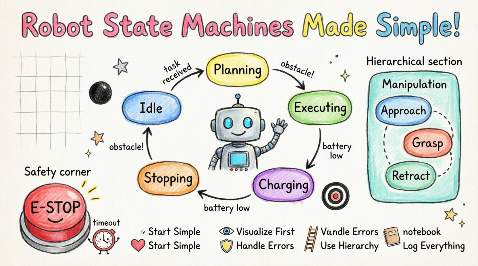
The robot begins in an Idle state. It waits for a task assignment. Once assigned, it transitions to Planning. Upon completion of the path calculation, it moves to Executing. If an obstacle appears, it must handle it without crashing.
The following table outlines the specific states and their corresponding responsibilities.
| State Name | Active Behavior | Exit Condition | Entry Action |
|---|---|---|---|
| Idle | Listening for commands | NewTaskReceived | InitializeSensors |
| Planning | Calculating path | PathValid | LockMotors |
| Executing | Driving along path | ObstacleDetected OR TaskComplete | StartDriveLoop |
| Stopping | Braking system | VelocityZero | ApplyBrakes |
| Charging | Connecting to dock | BatteryFull | EngageDockingMech |
⚙️ Managing Complex Behaviors with Hierarchical States
As robots become more advanced, flat state machines become difficult to manage. A single state might need to handle dozens of sub-conditions. This is where Hierarchical State Machines shine.
Consider a robotic arm. The main state might be Manipulation. Inside this state, there are sub-states for Grasping, Lifting, and Placing. If the robot needs to switch to Calibration, it can exit the entire Manipulation hierarchy and return later.
- Modularity: Breaks down complex logic into manageable chunks.
- Reusability: Sub-machines can be reused across different main states.
- Clarity: Reduces the visual clutter of a large diagram.
Example: Robotic Arm Hierarchy
When the robot is in the Manipulation state, it is actually in one of three sub-states:
- Approach: Moving the gripper to the object.
- Grasp: Closing the fingers.
- Retract: Moving the object to a new location.
If a safety override is triggered during any of these sub-states, the robot transitions out of the Manipulation parent state entirely, ensuring safety protocols are met regardless of the specific sub-task.
🛡️ Safety and Error Handling in State Machines
Robotics involves physical hardware. Errors are not just software bugs; they can be physical hazards. State machines are uniquely suited to handle safety because they define explicit paths for failure.
1. The Emergency Stop State ⚠️
Every robotic system requires a high-priority state for emergencies. This state is usually accessible from any other state via a specific event, such as E-Stop_Pressed.
- Priority: This transition overrides all other logic.
- Behavior: Motors are cut, brakes are applied, and the system waits for human intervention.
- Return: The system cannot leave this state until a manual reset is confirmed.
2. Timeout Handling ⏱️
Sometimes a robot gets stuck. A state might be waiting for a sensor input that never arrives. State machines can include internal timers.
- Event: Timer expires.
- Action: Transition to a Recovery state.
- Logic: Attempt to reset the mechanism or request help.
3. Error States 🚫
Distinguish between a Transition Failure and a State Failure.
- Transition Failure: The condition to move states was not met.
- State Failure: The action within the state failed (e.g., motor overheating).
Designing distinct error states allows the robot to report the specific nature of the problem rather than just freezing.
📊 Comparing Flat vs. Hierarchical Designs
Selecting the right structure affects maintainability. A flat design works for simple agents, while hierarchical designs suit complex systems.
| Feature | Flat State Machine | Hierarchical State Machine |
|---|---|---|
| Complexity | Low. Best for simple logic. | High. Best for complex logic. |
| Scalability | Poor. Diagrams become tangled quickly. | Good. Sub-states contain details. |
| Debugging | Easy for small systems. | Requires tracing parent/child paths. |
| Reusability | Low. | High. Sub-states can be copied. |
| Visual Clarity | Clear for < 10 states. | Clear regardless of total states. |
🔧 Implementation Considerations
Translating a diagram into code requires discipline. The visual model should drive the software architecture.
1. Event Queue Management
Robots receive many events simultaneously. A queue ensures events are processed in order. The state machine should check the queue for the highest priority event available.
- Priority Levels: Safety events > Operational events > Logging events.
- Debounce: Ignore rapid, repeated triggers (e.g., a vibrating sensor).
2. State Variables
Not all data belongs in the state machine itself. Use variables to store data that persists across states, such as total distance traveled or current battery percentage.
- Local Variables: Specific to a state.
- Global Variables: Shared across the entire system.
3. Logging and Telemetry
Every transition should ideally generate a log entry. This is vital for post-mortem analysis if the robot behaves unexpectedly.
- Timestamp: When the change occurred.
- From/To: Source and destination states.
- Trigger: What caused the change.
🧪 Testing State Machines
Testing a state machine involves more than unit testing individual functions. You must verify the flows.
1. Transition Testing
Verify that every arrow in the diagram can be traversed. For every transition, verify the guard condition.
- Happy Path: Does the robot complete the task normally?
- Edge Cases: What happens if the battery dies mid-transition?
2. State Coverage
Ensure the robot visits every defined state during testing. If a state exists on paper but is never reached in code, it is dead weight.
3. Concurrency
Some systems have multiple state machines running simultaneously. For example, a navigation machine and a power management machine. Ensure they do not conflict.
- Shared Resources: Prevent race conditions.
- Communication: Define how machines talk to each other.
🚀 Common Pitfalls to Avoid
Even experienced engineers make mistakes when modeling logic. Be aware of these common traps.
- State Explosion: Creating too many granular states. Keep states meaningful. If a state has only one transition out, merge it.
- Circular Dependencies: Avoid loops that prevent the system from ever reaching a final state.
- Hidden Logic: Do not hide complex calculations inside a transition without documentation. Keep the diagram readable.
- Ignoring Initialization: Ensure the robot has a defined starting state. Never let it power on in an undefined state.
- Overusing History: While useful, history states can make debugging difficult. Use them only when resuming exact previous behavior is critical.
🔗 Integrating with Control Loops
State machines sit above the low-level control loops. They decide what to do, while control loops decide how to do it.
- High Level: State Machine (Decision making, mode switching).
- Mid Level: Path Planning (Generating trajectories).
- Low Level: PID Control (Motor speed, torque adjustment).
The state machine provides the command (e.g., MoveForward), and the control loop executes the physics. If the state machine switches to Stop, the control loop receives a new target velocity.
📈 Future-Proofing Your Designs
Robotics technology evolves rapidly. Your state machine design should be flexible enough to accommodate new sensors or capabilities.
- Extensibility: Design states that can accept new events without rewriting the whole structure.
- Documentation: Keep diagrams updated. An outdated diagram is worse than no diagram at all.
- Modularity: Separate navigation logic from manipulation logic. This allows one to be updated without affecting the other.
🧠 Summary of Best Practices
To create robust robotic systems, adhere to these principles when building your UML state machine diagrams.
- Start Simple: Define the core states first, then add complexity.
- Visualize First: Draw the logic before writing code.
- Define Guards: Be explicit about conditions for transitions.
- Handle Errors: Always have a path for failure and recovery.
- Use Hierarchy: Group related behaviors to reduce clutter.
- Log Everything: Maintain a record of state changes for analysis.
By following these guidelines, you create a foundation for systems that are not only functional but also maintainable and safe. The clarity provided by state machine diagrams reduces the cognitive load on the development team and ensures that the robot behaves predictably in the real world.
🤖 Final Thoughts on System Logic
Robotic systems are inherently complex. They interact with unpredictable physical environments. A well-structured state machine provides the necessary framework to manage this complexity. It transforms chaotic requirements into a structured, visual model that guides development from concept to deployment.
Focus on the transitions. The states are static, but the transitions represent the dynamic nature of the robot’s operation. Pay close attention to the events that trigger these transitions. They are the interface between the robot and its environment.
As you develop your skills, you will find that state machines are not just a documentation tool but a thinking tool. They force you to consider every possibility before the robot ever moves. This proactive approach to design is what separates reliable autonomous systems from prototypes that only work in a vacuum.
