


Introduction to UML
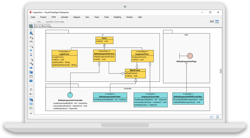
Imagine you’re part of a team building a complex software system. How do you ensure everyone understands the design? Enter UML, the Unified Modeling Language, a standardized way to visualize, specify, construct, and document software systems. UML provides a common language for software developers, allowing them to communicate ideas, design systems, and manage complexity effectively. It is widely used in software engineering, systems architecture, and business process modeling.
History of UML
UML was developed in the mid-1990s by combining the best practices from several object-oriented modeling techniques, including OMT (Object Modeling Technique), Booch, and OOSE (Object-Oriented Software Engineering). The first version, UML 1.0, was released in 1997 by the Object Management Group (OMG) (OMG UML). Since then, UML has evolved through several versions, with the current standard being UML 2.5.1, released in December 2017. This version includes minor updates but maintains the core principles of earlier versions.
Why Use UML?
In today’s software development landscape, systems are becoming increasingly complex, with distributed architectures, concurrent processes, and security concerns. UML addresses these challenges by providing a visual language that helps manage this complexity. Its key benefits include:
-
Improved Communication: UML diagrams serve as a universal language for stakeholders, including developers, analysts, testers, and clients.
-
Design Clarity: It allows teams to visualize system structure and behavior before implementation.
-
Requirement Validation: UML helps ensure that the system meets user and business requirements.
-
Documentation: It provides a standardized way to document systems, making maintenance and updates easier.
Overview of UML Diagrams
UML includes 14 types of diagrams, divided into two categories: structure diagrams and behavior diagrams. These diagrams help model different aspects of a system, from its static structure to its dynamic behavior.
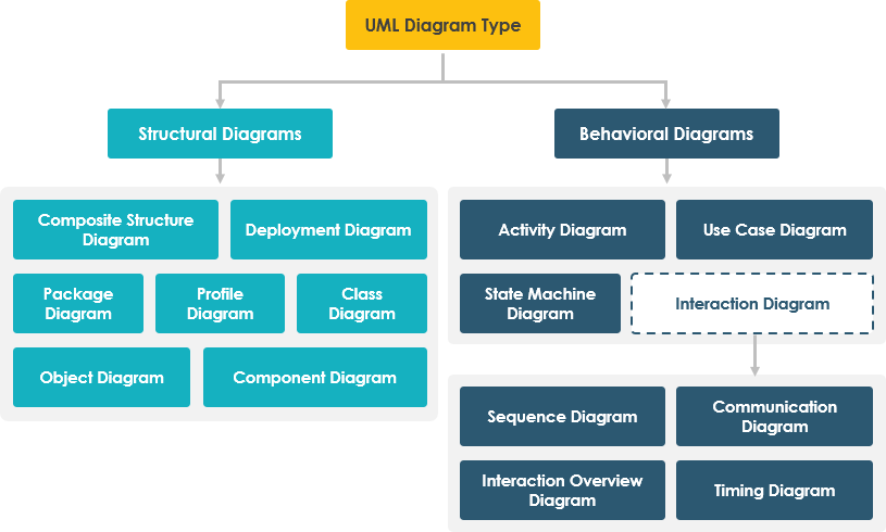
Structure Diagrams
Structure diagrams show the static structure of the system and its parts on different abstraction and implementation levels.
|
Diagram Type |
Description |
|---|---|
|
Class Diagram |
Shows the structure of classes, their attributes, and methods. |
|
Component Diagram |
Represents the organization and dependencies among components. |
|
Deployment Diagram |
Models the physical deployment of artifacts on nodes (e.g., servers, devices). |
|
Object Diagram |
Shows instances of classes and their relationships at a specific time. |
|
Package Diagram |
Organizes elements into packages and shows dependencies between them. |
|
Composite Structure Diagram |
Depicts the internal structure of a classifier (e.g., a class or component). |
|
Profile Diagram |
Defines extensions to UML, allowing customization for specific domains or platforms. |
Behavior Diagrams
Behavior diagrams illustrate the dynamic behavior of the system, showing how it changes over time.
|
Diagram Type |
Description |
|---|---|
|
Use Case Diagram |
Describes the functionality of the system from the user’s perspective. |
|
Activity Diagram |
Models the flow of actions in a process, similar to a flowchart. |
|
State Machine Diagram |
Shows the states of an object and the transitions between them. |
|
Sequence Diagram |
Depicts the interaction between objects over time, focusing on message exchanges. |
|
Communication Diagram |
Shows the interactions between objects, emphasizing their relationships. |
|
Interaction Overview Diagram |
Provides a high-level view of interactions between objects. |
|
Timing Diagram |
Focuses on the timing of messages between objects, useful for real-time systems. |
Key Concepts and Terms
UML introduces several key concepts that are essential for understanding its diagrams:
-
Class: A blueprint for creating objects, defining their attributes (data) and methods (functions).
-
Association: A relationship between classes, indicating how they are connected.
-
Aggregation: A special type of association where one class is composed of others (e.g., a car is made of wheels).
-
Use Case: A description of how a user interacts with the system to achieve a specific goal.
-
Actor: A role played by a user, system, or external entity that interacts with the system.
These terms are integrated into the explanations of diagrams for better flow and understanding.
Learning Resources
For those interested in delving deeper into UML, here are some recommended resources as of 2025:
-
Books:
-
UML Distilled by Martin Fowler (UML Distilled): A concise guide to understanding and applying UML, suitable for beginners and experienced users.
-
Applying UML and Patterns by Craig Larman (Applying UML): Combines UML with design patterns for practical software design.
-
SysML Distilled by Lenny Delligatti (SysML Distilled): Focuses on Systems Modeling Language (SysML), an extension of UML for systems engineering.
-
-
Online Courses:
-
UML Class Diagrams for Programmers by Riaan Nel (UML Course): Teaches how to read and create UML class diagrams, with practical examples.
-
Various tutorials and courses on platforms like Coursera, Udemy, and edX, covering UML fundamentals and advanced topics.
-
These resources provide a mix of theoretical knowledge and hands-on practice, making them ideal for both beginners and professionals.
Conclusion
UML is a powerful tool for software developers, providing a standardized way to visualize, specify, construct, and document software systems. By understanding its history, benefits, and diagram types, you can effectively use UML to improve your software design and development processes. Whether you’re a beginner or an experienced developer, mastering UML can enhance your ability to communicate ideas, manage complexity, and build robust systems.
References
- Visual Paradigm
- UML Practical Guide
- Agile Tutorial
- Project Management Process Tool
- Large Scale Scrum Software
- Charts
- Agile Project Management
- Agile Software Development
- User Story Mapping
- Agile Backlog
- Sprint Planning
- Product Backlog
- Enterprise Architecture
- TOGAF ADM Tutorial
- ArchiMate Modeling Tool
- As-Is/To-Be Business Process
- DoDAF Framework
- NATO Architecture Framework
- MODAF Tool
- BPMN
- Customer Journey Mapping
- Code Engineering
- ORM
- REST API
- UX Design and Wireframe Tools
- UML
- Data Flow Diagram
- Entity Relationship Diagram
- SysML Diagram Tool
- SoaML Diagrams
- Database Engineering Tools
- Reverse Engineering
- Use Case Diagram
- Visual Paradigm Online
- Charts, Data Widgets, and Maps
- Team Collaboration Toolset
- Online Diagram Tool
- Spreadsheet Editor
- Forms
- Mind Mapping Diagram and Tools
- Generating Reports
- Publish Project
- Textual Analysis
- On-Demand Model ETL
- Scaling Agile Frameworks Comparison
- ArchiMate
- DevOps Diagram
