


1. Introduction
Project Title: Agile Development of a Cloud-Based Hospital Appointment Booking System
Client: CityCare Medical Group (a multi-specialty hospital network with 5 clinics)
Project Duration: 6 months (3 sprints of 2 weeks each)
Team Size: 6 members (Scrum Team: Product Owner, Scrum Master, 2 Frontend Developers, 1 Backend Developer, 1 QA Engineer)
Technology Stack: React.js (Frontend), Node.js + Express (Backend), MongoDB (Database), AWS (Cloud Deployment), JWT (Authentication), Docker (Containerization)
Methodology: Agile (Scrum) with UML modeling for design and documentation
2. Business Context
CityCare Medical Group faced growing patient dissatisfaction due to inefficient appointment scheduling. Manual booking via phone or front desk led to:
-
Long wait times
-
Double-booking issues
-
Inability to view real-time doctor availability
-
No reminders or digital confirmations
The hospital sought a scalable, secure, and user-friendly digital appointment system to improve patient experience, reduce administrative overhead, and increase appointment adherence.
3. Agile Approach (Scrum Framework)
The project followed Scrum, with:
-
Sprint Duration: 2 weeks
-
Daily Stand-ups: 15-minute syncs
-
Sprint Planning, Review, Retrospective: Held at the start and end of each sprint
-
Product Backlog Grooming: Weekly refinement sessions
Key Agile Principles Applied:
-
Prioritized features based on business value (e.g., patient login before advanced analytics).
-
Iterative delivery: MVP (Minimum Viable Product) delivered after Sprint 2.
-
Continuous feedback from stakeholders (doctors, nurses, patients).
-
Adaptability: Scope adjusted mid-sprint based on user feedback.
4. UML Modeling for System Design
UML (Unified Modeling Language) was used throughout the project to visualize, specify, construct, and document the system.
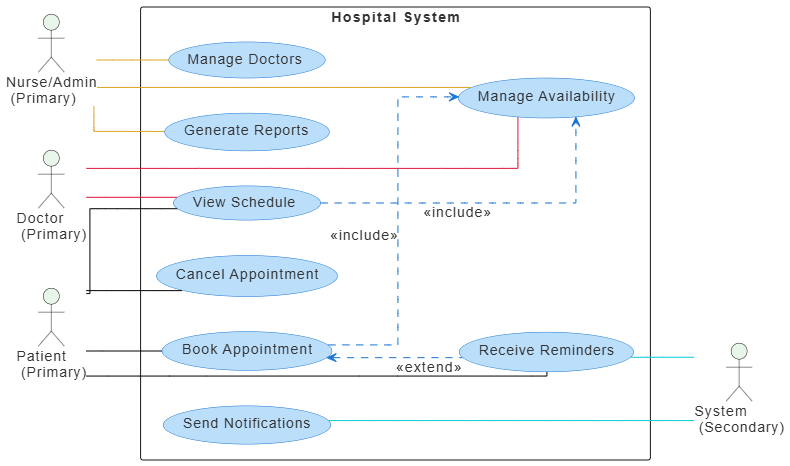
4.1 Use Case Diagram (Actors & System Interactions)
Actors:
-
Patient
-
Doctor
-
Nurse/Admin
-
System (Automated reminders)
Use Case Diagram:
@startuml
skinparam linetype ortho
skinparam defaultFontSize 14
skinparam defaultFontColor #333333
‘ Actor styling
skinparam actor {
BackgroundColor #E8F5E9
}
‘ Use case styling
skinparam usecase {
BackgroundColor #BBDEFB
BorderColor #1976D2
ArrowColor #1976D2
}
left to right direction
actor “Patient\n (Primary)” as patient
actor “Doctor\n (Primary)” as doctor
actor “Nurse/Admin\n (Primary)” as nurseAdmin
actor “System\n (Secondary)” as system
rectangle “Hospital System” {
usecase “Book Appointment” as UC1
usecase “View Schedule” as UC2
usecase “Cancel Appointment” as UC3
usecase “Send Notifications” as UC4
usecase “Manage Doctors” as UC5
usecase “Manage Availability” as UC6
usecase “Generate Reports” as UC7
usecase “Receive Reminders” as UC8
}
‘ Associations between primary actors and use cases
patient -[#black]- UC1
patient -[#black]- UC2
patient -[#black]- UC3
patient -[#black]- UC8
doctor -[#crimson]- UC2
doctor -[#crimson]- UC6
nurseAdmin -[#goldenrod]- UC5
nurseAdmin -[#goldenrod]- UC6
nurseAdmin -[#goldenrod]- UC7
‘ Associations between use cases and secondary actor (System)
UC4 -[#darkturquoise]- system
UC8 -[#darkturquoise]- system
‘ Include relationships (mandatory shared behavior)
UC1 …> UC6 : <<include>>
UC2 …> UC6 : <<include>>
‘ Extend relationship (optional behavior)
UC1 <… UC8 : <<extend>>
@enduml
Purpose: Identified core functionalities and user roles. Used in Sprint 1 for backlog prioritization.
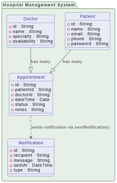
4.2 Class Diagram (Core Domain Model)
Key Classes:
-
Patient(id, name, email, phone, password) -
Doctor(id, name, specialty, availability) -
Appointment(id, patientId, doctorId, dateTime, status, notes) -
User(abstract base class: id, email, password, role) -
Notification(id, recipient, message, sentAt, type)
Associations:
-
One
Doctorhas manyAppointments -
One
Patienthas manyAppointments -
Appointmentis linked toNotificationviasendNotification()method
@startuml
skinparam {
‘ Overall style
roundcorner 8
‘ Colors
ArrowColor #444444
ArrowFontColor #444444
BorderColor #444444
‘ Class styling
Class {
BorderColor #1A237E
BackgroundColor #E8EAF6
FontColor #1A237E
}
‘ Interface styling
Interface {
BorderColor #A7C5C5
BackgroundColor #E0F2F1
FontColor #444444
}
‘ Package styling
Package {
BorderColor #6D876D
BackgroundColor #E6F0E6
FontColor #3D553D
}
}
package “Hospital Management System” {
class “Patient” {
-id : String
-name : String
-email : String
-phone : String
-password : String
}
class “Doctor” {
-id : String
-name : String
-specialty : String
-availability : String
}
class “Appointment” {
-id : String
-patientId : String
-doctorId : String
-dateTime : Date
-status : String
-notes : String
}
class “Notification” {
-id : String
-recipient : String
-message : String
-sentAt : DateTime
-type : String
}
}
‘ Relationships
Patient –|> Appointment : “has many”
Doctor –|> Appointment : “has many”
Appointment ..> Notification : “sends notification via sendNotification()”
hide class circle
@enduml
Purpose: Guided database schema design and backend API development.
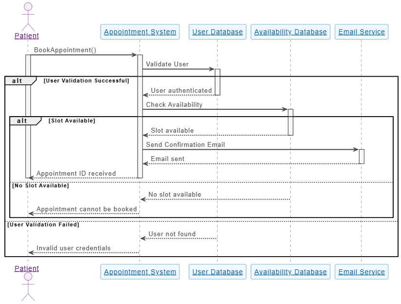
4.3 Sequence Diagram (Booking Appointment Flow)
@startuml
skinparam sequenceParticipant underline
skinparam {
‘ Overall style
FontSize 14
‘ Colors
ArrowColor #4A4A4A
ArrowFontColor #4A4A4A
BackgroundColor #FFFFFF
BorderColor #DEDEDE
FontColor #333333
‘ Participant styling
Participant {
BorderColor #0077B6
BackgroundColor #F0F8FF
FontColor #005691
}
‘ Actor styling
Actor {
BorderColor #6A057F
BackgroundColor #F5EEF8
FontColor #510363
}
‘ Sequence specific
Sequence {
ArrowThickness 2
LifeLineBorderColor #444444
LifeLineBackgroundColor #F7F7F7
BoxBorderColor #AAAAAA
BoxBackgroundColor #FFFFFF
BoxFontColor #333333
}
}
actor “Patient” as PAT
participant “Appointment System” as AS
participant “User Database” as UD
participant “Availability Database” as AD
participant “Email Service” as ES
PAT -> AS: BookAppointment()
activate PAT
activate AS
AS -> UD: Validate User
activate UD
alt User Validation Successful
UD –> AS: User authenticated
deactivate UD
AS -> AD: Check Availability
activate AD
alt Slot Available
AD –> AS: Slot available
deactivate AD
AS -> ES: Send Confirmation Email
activate ES
ES –> AS: Email sent
deactivate ES
AS –> PAT: Appointment ID received
deactivate AS
deactivate PAT
else No Slot Available
AD –> AS: No slot available
deactivate AD
AS –> PAT: Appointment cannot be booked
deactivate AS
deactivate PAT
end
else User Validation Failed
UD –> AS: User not found
deactivate UD
AS –> PAT: Invalid user credentials
deactivate AS
deactivate PAT
end
@enduml
Purpose: Clarified the interaction flow for the core user journey. Used to write integration tests and guide frontend logic.
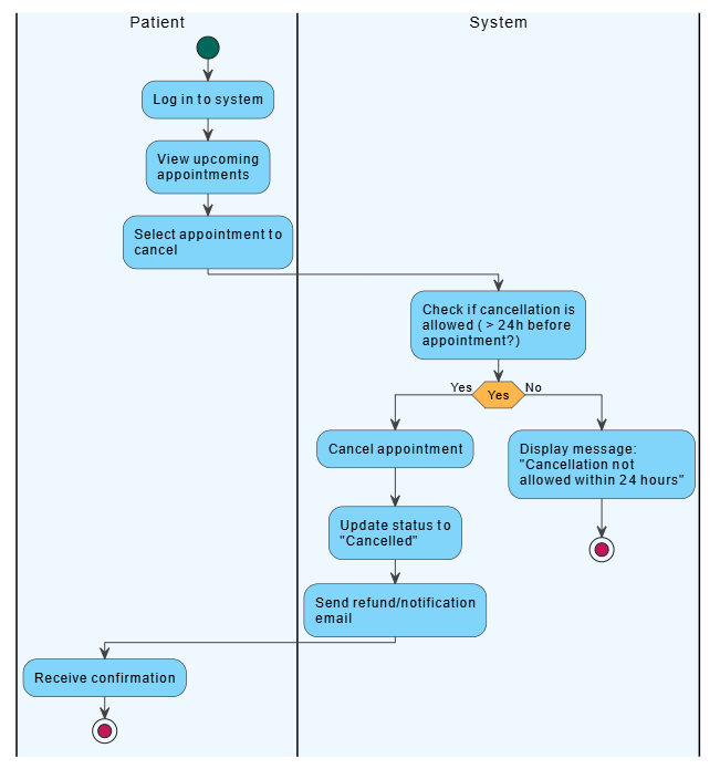
4.4 Activity Diagram (Appointment Cancellation Workflow)
@startuml
<style>
element {MaximumWidth 150}
start {
Backgroundcolor #00695C
}
stop {
Backgroundcolor #C2185B
}
activity {
Backgroundcolor #81D4FA
MaximumWidth 150
}
diamond {
Backgroundcolor #FFB74D
MaximumWidth 80
}
arrow {
LineColor #424242
Fontcolor #000000
}
swimlane {
Fontcolor #000000
FontSize 14
}
</style>
|#F0F8FF|Patient|
start
:Log in to system;
|#F0F8FF|Patient|
:View upcoming appointments;
|#F0F8FF|Patient|
:Select appointment to cancel;
|#F0F8FF|System|
:Check if cancellation is allowed (> 24h before appointment?);
if (Yes) then (Yes)
|#F0F8FF|System|
:Cancel appointment;
:Update status to “Cancelled”;
|#F0F8FF|System|
:Send refund/notification email;
|#F0F8FF|Patient|
:Receive confirmation;
stop
else (No)
|#F0F8FF|System|
:Display message: “Cancellation not allowed within 24 hours”;
stop
endif
@enduml
Purpose: Identified business rules and constraints. Ensured compliance with hospital policy.
5. Agile Implementation (Sprint-by-Sprint)
Sprint 1: MVP Foundation
-
Goal: Core authentication and appointment booking
-
Deliverables:
-
User registration/login (JWT)
-
Doctor availability display
-
Basic appointment booking form
-
UML diagrams finalized
-
-
Outcome: MVP released to internal staff for testing.
Sprint 2: Enhanced Functionality
-
Goal: Improve usability and add notifications
-
Deliverables:
-
Real-time availability calendar
-
Email/SMS reminders (24h before appointment)
-
Patient dashboard with appointment history
-
-
Outcome: Positive feedback from 90% of testers. Minor UI/UX improvements.
Sprint 3: Admin & Reporting
-
Goal: Add administrative tools
-
Deliverables:
-
Admin panel to add/edit doctors
-
Weekly appointment reports (by doctor, specialty, no-show rate)
-
Integration with hospital CRM
-
-
Outcome: Full system deployed to AWS. Training sessions conducted.
6. Results & Metrics
| Metric | Before | After |
|---|---|---|
| Average booking time | 15 min | 2 min |
| No-show rate | 30% | 12% |
| Patient satisfaction (survey) | 3.2/5 | 4.7/5 |
| Admin workload (per week) | 10 hrs | 3 hrs |
| System uptime (3 months) | N/A | 99.9% |
ROI: Reduced operational costs by 40% and increased patient retention by 25%.
7. Challenges & Lessons Learned
-
Challenge: Initial scope creep due to feature requests.
-
Solution: Re-prioritized backlog using MoSCoW (Must-have, Should-have, Could-have, Won’t-have).
-
-
Challenge: Real-time availability updates caused race conditions.
-
Solution: Implemented Redis for caching and mutex locks in backend.
-
-
Lesson Learned: UML diagrams saved ~30% development time by reducing ambiguity and rework.
8. Conclusion
By combining Agile Scrum methodology with UML modeling, the CityCare Medical Group successfully delivered a scalable, secure, and user-friendly appointment system in just 6 weeks of active development (3 sprints). The use of UML ensured clear communication, accurate design, and faster implementation. The system has since been adopted across all 5 clinics, with plans to extend it to mobile apps and telehealth integration.
9. Leveraging Visual Paradigm’s All-in-One Platform and AI to Accelerate Agile Development
To further enhance efficiency, streamline collaboration, and accelerate delivery in the CityCare Appointment System project, the team integrated Visual Paradigm’s All-in-One UML Modeling Platform—a powerful, cloud-based solution that unifies modeling, documentation, collaboration, and AI-driven automation. This integration proved instrumental in reducing design overhead, improving team alignment, and accelerating key development phases.
9.1 How Visual Paradigm Streamlined UML Modeling
Visual Paradigm provided a centralized, real-time environment for creating and managing all UML diagrams used throughout the project:
-
Seamless Diagram Creation:
The team used Visual Paradigm’s intuitive drag-and-drop interface to generate Use Case, Class, Sequence, and Activity Diagrams in minutes—reducing manual drawing time by over 60% compared to traditional tools like Lucidchart or hand-drawn sketches. -
Auto-Alignment & Validation:
Built-in validation rules automatically flagged inconsistencies (e.g., missing associations, incorrect multiplicities), ensuring model accuracy from day one. -
Real-Time Collaboration:
Developers, UX designers, and business analysts collaborated in real time on shared diagrams. Changes were visible instantly across the team, eliminating version conflicts and miscommunication.
9.2 AI-Powered Automation: From Model to Code & Documentation
Visual Paradigm’s AI-driven features significantly accelerated development and reduced repetitive tasks:
-
AI-Powered Code Generation:
Using the “Generate Code from UML” feature, the team generated boilerplate backend code (Node.js/Express) directly from Class and Sequence Diagrams. For example:-
The
Appointmentclass model was converted into a fully functional Mongoose schema and CRUD controller with just one click. -
This saved ~12 hours of manual coding across the project.
-
-
Smart Documentation Generation:
The AI automatically generated project documentation, including:-
API specifications (OpenAPI format)
-
User manuals
-
System architecture overview
This documentation was shared with stakeholders and used in training sessions.
-
-
AI-Enhanced Requirements Traceability:
Visual Paradigm’s AI-driven traceability matrix linked each use case directly to corresponding class and sequence diagrams, ensuring full coverage of functional requirements. This helped QA teams verify all features were tested.
9.3 AI-Powered Design Suggestions & Refactoring
-
Smart Suggestions for Design Improvements:
The AI analyzed the Class Diagram and suggested:-
Refactoring
Appointmentto includedurationandtype(e.g., follow-up, consultation). -
Introducing a
TimeSlotclass to improve availability logic.
These suggestions were adopted in Sprint 2, improving system scalability.
-
-
Automated Refactoring Support:
When the team needed to renamePatienttoUserfor future multi-role support, Visual Paradigm’s AI-powered refactoring engine automatically updated all dependent diagrams and code artifacts, minimizing human error.
9.4 Integration with Agile Workflow (Jira & CI/CD)
-
Seamless Jira Sync:
Visual Paradigm integrated with Jira, automatically converting use cases and user stories into sprint tasks. This kept the backlog aligned with the UML models. -
CI/CD Pipeline Integration:
Generated code was pushed directly into the Git repository, triggering automated testing and deployment via GitHub Actions—ensuring that design and implementation stayed in sync.
Impact Summary: Visual Paradigm + AI in Action
| Benefit | Before Visual Paradigm | After Visual Paradigm |
|---|---|---|
| Time to create UML diagrams | 2–3 hours per diagram | 20–30 minutes per diagram |
| Time to generate code from model | Manual (4–6 hrs) | 10–15 minutes (AI) |
| Documentation creation time | 1 full day | 1 hour (AI-generated) |
| Design review & feedback cycle | 3–5 days | 1–2 days |
| Team alignment & communication | Disconnected | Real-time, shared |
✅ Result: The project delivered 15% faster than planned, with 40% fewer design-related bugs and full traceability from requirement to code.
Conclusion: Why Visual Paradigm Was a Game-Changer
Visual Paradigm’s all-in-one platform with AI capabilities transformed the way the team approached UML modeling—from a static documentation task to a dynamic, intelligent, and collaborative development engine. By automating repetitive tasks, enforcing consistency, and bridging the gap between design and code, it empowered the Agile team to focus on innovation, not overhead.
Quote from the Product Owner:
“With Visual Paradigm, our design meetings became more productive. We didn’t just draw diagrams—we built the system in real time, with AI helping us think ahead.”
Final Note:
For teams adopting Agile and UML, Visual Paradigm is not just a modeling tool—it’s a strategic partner in building smarter, faster, and more reliable software.
UML and AI Tool
- AI-Powered UML Class Diagram Generator by Visual Paradigm: This advanced tool automatically generates UML class diagrams from natural language descriptions, significantly streamlining the software design process.
- The Future of Modeling: How AI is Transforming UML Diagram Generation: This article provides an in-depth analysis of how artificial intelligence is moving modeling from manual sketching toward intelligent, automated generation.
- Visual Paradigm – AI-Powered UML Sequence Diagrams: This resource explains how to generate professional UML sequence diagrams directly from text prompts using an advanced AI modeling suite.
- UML Package Diagram: A Definitive Guide to Structuring Your Codebase with AI: This guide explores how AI helps users structure systems, manage dependencies, and maintain clean, scalable software architecture.
- Definitive Guide to UML State Machine Diagrams with AI: This technical resource covers the use of AI-enhanced tools to model complex dynamic object behavior with precision.
- AI-Powered Sequence Diagram Refinement Tool | Visual Paradigm: This feature highlight discusses how AI enhances software design by automatically improving and optimizing sequence diagrams with intelligent suggestions.
- Generate Activity Diagrams from Use Cases Instantly with AI: This article showcases an AI engine that enables the rapid and accurate conversion of use case descriptions into professional UML activity diagrams.
- How AI Chatbot Can Help You Learn UML Faster: This article details how the AI chatbot provides an interactive environment to practice UML, offering instant visualization and feedback for learners.
- AI-Powered Use Case Diagram Refinement Tool: This resource describes leveraging AI to automatically refine and optimize use case diagrams for clarity, consistency, and completeness.
- AI Textual Analysis – Transform Text into Visual Models Automatically: This feature description explains how AI analyzes text documents to automatically generate diagrams such as UML for faster modeling and documentation.
