


Introduction
In today’s rapidly evolving software development landscape, effective communication and visualization of complex systems is not just beneficial—it’s essential. Unified Modeling Language (UML) has emerged as the industry-standard visual modeling language that bridges the gap between abstract requirements and concrete implementation. Since its proposal to the Object Management Group (OMG) in January 1997, UML has revolutionized how developers, architects, and stakeholders conceptualize, design, and document both software and non-software systems.
This comprehensive guide explores UML as a powerful product in the software development toolkit, examining its core features, practical applications, and the complete suite of 14 diagram types that enable teams to capture architectural, behavioral, and structural aspects of any system. Whether you’re modeling a multi-tiered enterprise application or optimizing manufacturing processes, UML provides the visual vocabulary to transform complex ideas into clear, actionable blueprints.

What is UML? Core Features & Capabilities
Feature Overview
UML functions as a general-purpose modeling language with several key capabilities:
-
Standardized Visual Language: Created and maintained by the Object Management Group (OMG), UML 1.0 specification draft was proposed in January 1997, establishing a universal standard for system modeling
-
Beyond Software Boundaries: While primarily used for software systems, UML extends to non-software applications like manufacturing process flows and business workflows
-
Code Generation Ready: Though not a programming language itself, UML diagrams can be transformed into executable code across various programming languages through specialized tools
-
Object-Oriented Foundation: Built on object-oriented concepts and methodology, making it ideal for modeling complex systems through objects, classes, and their relationships
Key Benefits
✓ Universal Accessibility: Designed for developers, business users, analysts, and stakeholders alike
✓ Multi-Perspective Modeling: Supports design, implementation, deployment, and process views
✓ Comprehensive Coverage: Captures architectural, behavioral, and structural system aspects
✓ Industry Standard: Non-proprietary and open to all, with widespread adoption across organizations and tool vendors
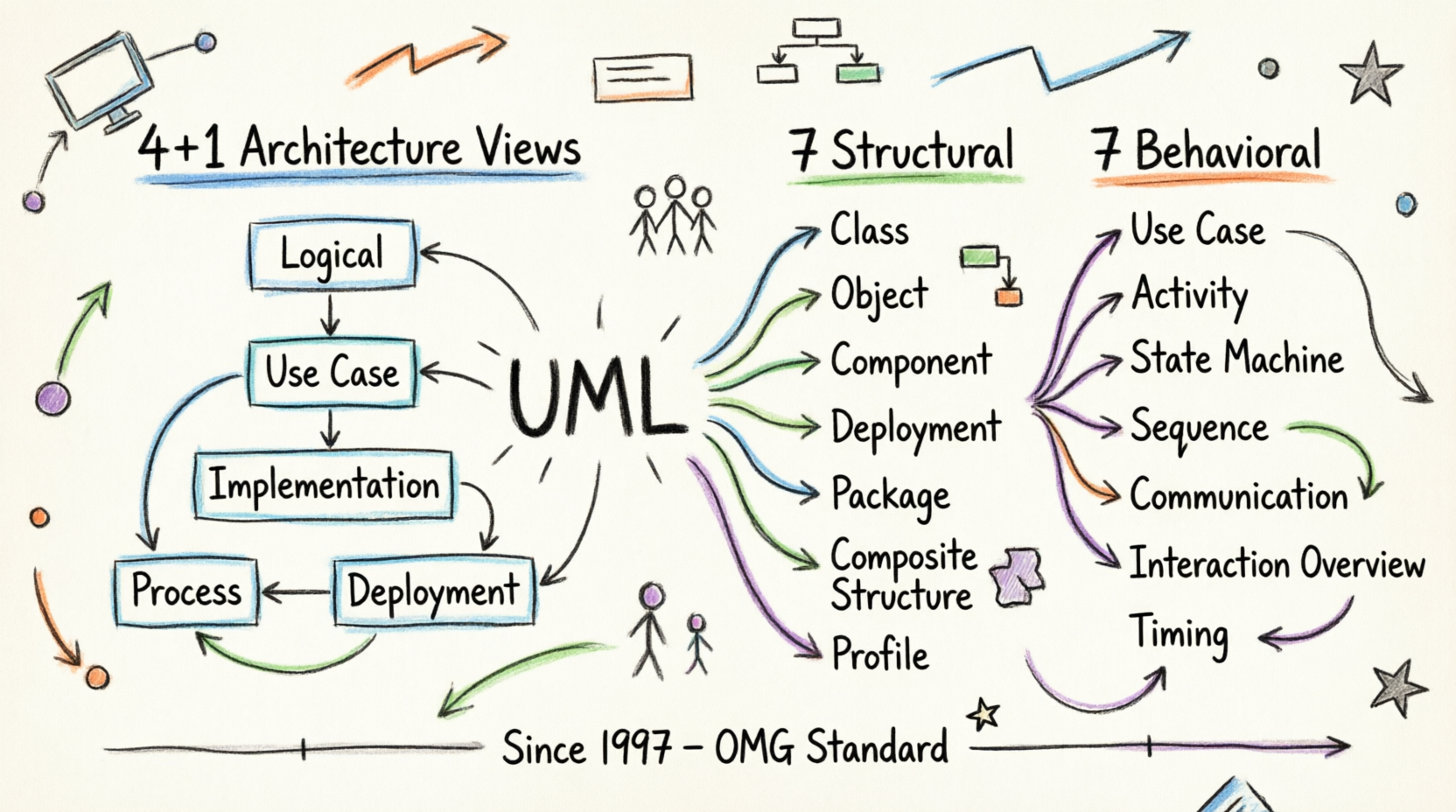
Modeling Architecture Views: The 4+1 View Model
Product Feature: Multi-Stakeholder Perspective Support
Real-world systems serve diverse users—developers, testers, business analysts, and executives. UML’s architecture modeling capability addresses this through the 4+1 Views of Software Architecture, ensuring every stakeholder sees the system from their relevant perspective.
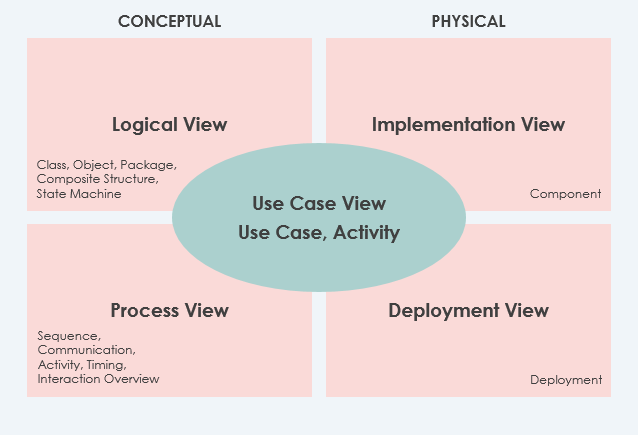
The Five Architectural Views
1. Use Case View (The Central Hub)
Purpose: Describes system functionality, external interfaces, and principal users
Status: MANDATORY – All architectural elements derive from requirements
Key Component: Use-Case Model
2. Logical View
Purpose: Shows system structure in terms of implementation units
Elements: Packages, classes, interfaces, dependencies, and relationships
Status: MANDATORY
Best For: Understanding design-level architecture
3. Implementation View
Purpose: Organizes development artifacts in the file system
Elements: Files, directories, configuration items
Status: Optional
Best For: Development team organization and version control
4. Process View
Purpose: Describes run-time system structure and behavior
Elements: Processes, threads, EJBs, servlets, DLLs, data stores, queues
Status: Optional
Best For: Performance and reliability analysis
5. Deployment View
Purpose: Maps system components to hardware infrastructure
Status: Optional
Best For: System engineers and infrastructure planning
Bonus: Data View
Purpose: Specialization of logical view for persistence-heavy systems
Best For: Systems requiring explicit data model translation
The Complete UML Diagram Suite: 14 Types Explained
UML diagrams are categorized into two primary families: Structural Diagrams (static) and Behavioral Diagrams (dynamic).
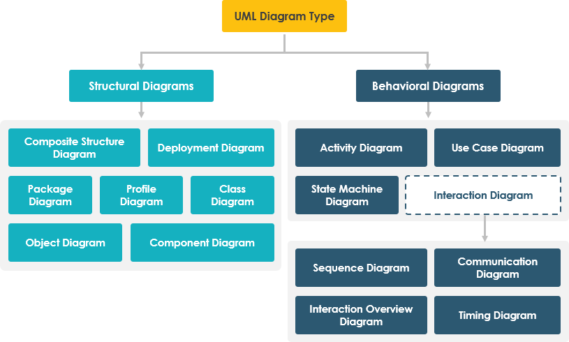
STRUCTURAL DIAGRAMS (7 Types)
1. Class Diagram ⭐ Most Popular
Rating: ★★★★★
Use Case: Object-oriented system design and documentation
Key Features:
-
Describes objects, attributes, and functions
-
Represents static system view
-
Directly mappable to object-oriented programming languages
-
Multiple diagrams combine to represent entire system
Best For: Developer community, system architects, code documentation
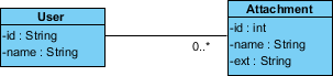
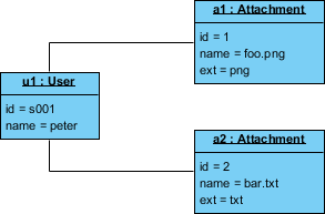
2. Object Diagram
Rating: ★★★★☆
Use Case: Instance-level system snapshots
Key Features:
-
Instance of a class diagram at a specific moment
-
Shows concrete objects and links (not abstract classes)
-
Captures detailed system state at a point in time
-
Limited but powerful for demonstrating data structures
Best For: Showing examples, debugging, validating class designs
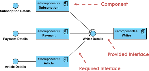
3. Component Diagram
Rating: ★★★★☆
Use Case: Static implementation view
Key Features:
-
Describes physical components (libraries, files, folders)
-
Implementation perspective focus
-
Supports forward and reverse engineering
-
Multiple diagrams represent complete system
Best For: System engineers, build management, deployment planning
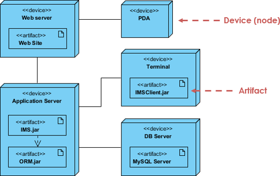
4. Deployment Diagram
Rating: ★★★★☆
Use Case: Hardware-software mapping
Key Features:
-
Shows nodes and their relationships
-
Static deployment view
-
Essential for software application development
-
System engineer primary tool
Best For: Infrastructure planning, network architecture, deployment strategies
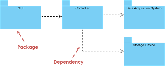
5. Package Diagram
Rating: ★★★★☆
Use Case: Organizing model elements
Key Features:
-
Shows packages and dependencies
-
Supports multi-layered/multi-tiered application models
-
Enables different system views
-
Organizes large-scale systems
Best For: Enterprise architecture, modular design, dependency management
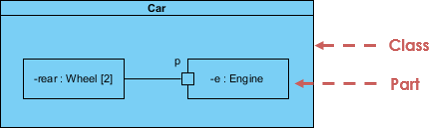
6. Composite Structure Diagram (UML 2.0+)
Rating: ★★★☆☆
Use Case: Internal class structure modeling
Key Features:
-
New artifact in UML 2.0
-
Micro point-of-view modeling
-
Shows internal parts, ports, and connectors
-
Depicts collaborations at runtime
-
Focuses on individual parts rather than whole classes
Best For: Complex component design, internal architecture visualization
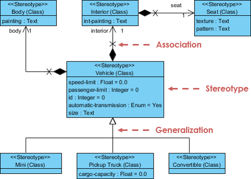
7. Profile Diagram
Rating: ★★★☆☆
Use Case: Domain-specific extensions
Key Features:
-
Creates domain and platform-specific stereotypes
-
Defines relationships between stereotypes
-
Supports composition and generalization
-
Visualizes tagged values
Best For: Custom modeling extensions, industry-specific adaptations
BEHAVIORAL DIAGRAMS (7 Types)
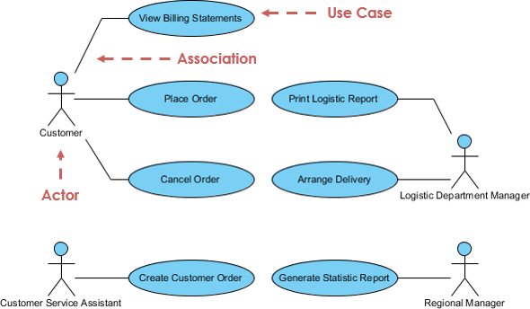
8. Use Case Diagram ⭐ Planning Essential
Rating: ★★★★★
Use Case: High-level requirements capture
Key Features:
-
Describes functional requirements
-
Models system functionality and environment
-
Consists of use cases, actors, and relationships
-
Powerful planning instrument
-
Used across all development phases
Best For: Requirements gathering, stakeholder communication, project planning
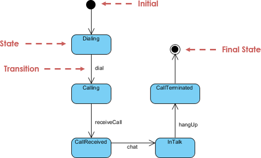
9. State Machine Diagram
Rating: ★★★★☆
Use Case: Object lifecycle modeling
Key Features:
-
Also known as statechart or state transition diagram
-
Developed by David Harel
-
Models entire object lifecycle
-
Shows states and transitions triggered by events
-
Supports forward and reverse engineering
Best For: Complex object behavior, event-driven systems, workflow modeling
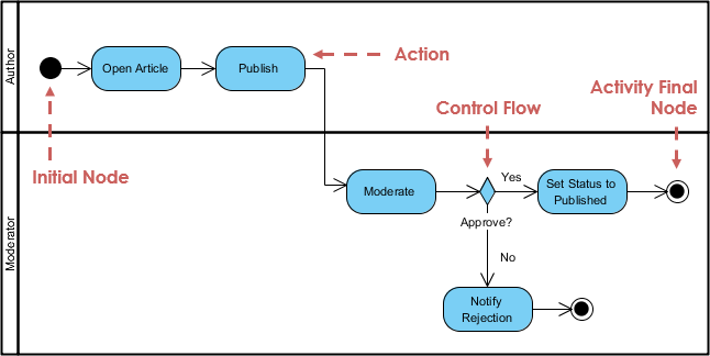
10. Activity Diagram
Rating: ★★★★☆
Use Case: Process and workflow modeling
Key Features:
-
Describes dynamic behavior and flow control
-
Models parallel, single, and concurrent flows
-
No message passing between activities
-
Models both computational and organizational processes
-
High-level business requirements view
Best For: Business process modeling, workflow design, algorithm visualization
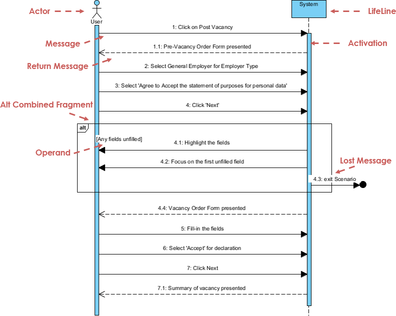
11. Sequence Diagram
Rating: ★★★★★
Use Case: Time-based object collaboration
Key Features:
-
Models collaboration based on time sequence
-
Shows object interactions in specific scenarios
-
Advanced visual modeling capabilities
-
Can be generated from use case descriptions
-
Complex diagrams created in few clicks
Best For: Detailed interaction design, API documentation, scenario modeling
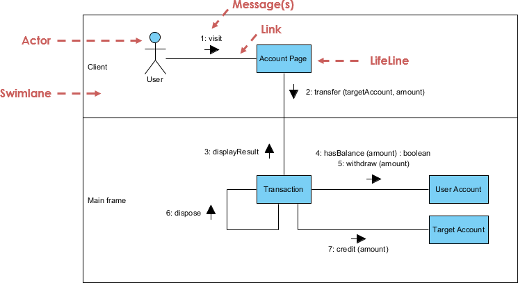
12. Communication Diagram
Rating: ★★★★☆
Use Case: Object collaboration focus
Key Features:
-
Similar to sequence diagram but collaboration-focused
-
Less emphasis on time sequence
-
Semantically equivalent to sequence diagrams
-
Convertible to/from sequence diagrams
-
Shows structural organization of objects
Best For: Understanding object relationships, collaboration patterns
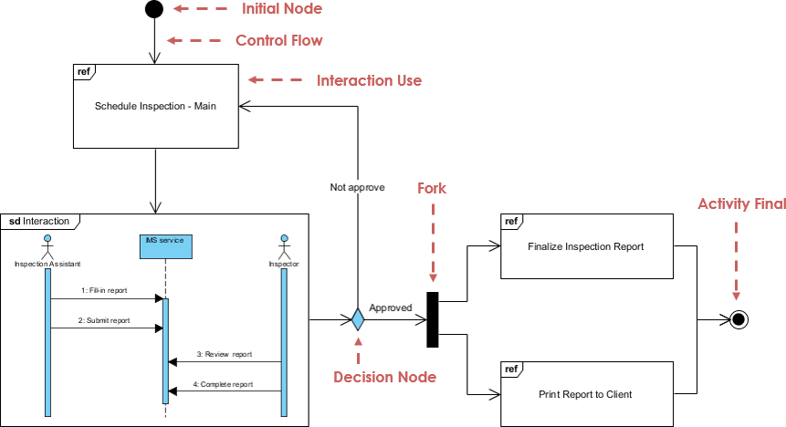
13. Interaction Overview Diagram
Rating: ★★★☆☆
Use Case: High-level interaction flow
Key Features:
-
Variant of activity diagram
-
Nodes represent interactions or interaction occurrences
-
Messages and lifelines hidden for clarity
-
Links multiple “real” diagrams
-
High navigability between diagrams
Best For: System overview, complex interaction orchestration
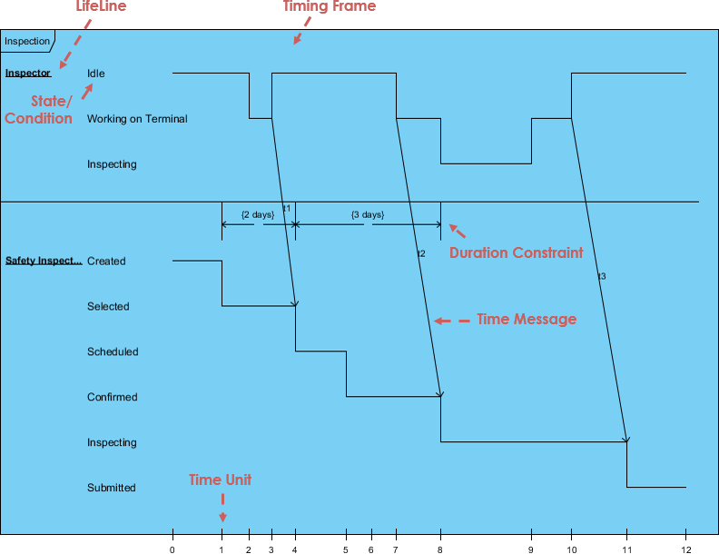
14. Timing Diagram
Rating: ★★★☆☆
Use Case: Time-constrained behavior
Key Features:
-
Special form of sequence diagram
-
Reversed axes (time increases left to right)
-
Lifelines in separate vertical compartments
-
Shows behavior over specific time periods
-
Precise timing constraints
Best For: Real-time systems, performance-critical applications, embedded systems
UML Product Strengths & Advantages
What Makes UML Stand Out
✅ Non-Proprietary & Open: Accessible to all users and scientific communities
✅ Built on Proven Methods: Incorporates semantics from Booch, OMT, OOSE, and other leading methodologies
✅ Industry Commitment: Widespread adoption by methodologists, organizations, and tool vendors
✅ Unified Approach:
-
Eliminates inconsequential differences between previous modeling languages
-
Unifies perspectives across business/software systems
-
Bridges requirements analysis, design, and implementation phases
The “Unified” Advantage
-
Standardization: Ends fragmentation in modeling languages
-
Comprehensive Coverage: Supports multiple system types, development phases, and internal concepts
-
Simple Yet Powerful: Modeling mechanism for all practical systems in complex environments
Modern UML Practice: AI-Powered Diagramming Tools
Applying UML principles in real-world software architecture can be challenging. Visual Paradigm’s AI-powered tools bridge the gap between abstract requirements and professional-grade diagrams, helping you visualize complex systems in a fraction of the time.
💬 AI Diagram Chatbot
Feature: Instant diagram drafting through natural conversation
Best For: Quickly capturing use case views and system behaviors
Use When: You need rapid prototyping or brainstorming sessions
🌐 AI WebApps
Feature: Step-by-step AI-guided workflows
Best For: Creating and evolving architecture from simple sketches to detailed implementation views
Use When: You need structured guidance through complex modeling tasks
⚡ AI Diagram Generator
Feature: Generate professional UML diagrams directly within Visual Paradigm Desktop
Best For: Ensuring full compliance with OMG standards
Use When: You need production-ready, standards-compliant diagrams
📝 OpenDocs
Feature: Modern knowledge management system with live AI-generated diagrams
Best For: Centralizing documents and embedding dynamic diagrams
Use When: You need integrated documentation with visual models
Ready to modernize your modeling process?
Explore the AI Diagramming Ecosystem →
Conclusion
Unified Modeling Language has proven itself as an indispensable tool in the modern software development arsenal. From its inception in 1997 to its current status as an OMG standard, UML has successfully unified disparate modeling approaches into a comprehensive, accessible, and powerful visual language.
The strength of UML lies not just in its 14 distinct diagram types, but in its ability to serve multiple stakeholders—from developers writing code to executives making strategic decisions. The 4+1 architectural view model ensures that every perspective is captured, while the combination of structural and behavioral diagrams provides a complete picture of both what a system is and how it behaves.
As software systems grow increasingly complex, the need for clear visualization and documentation becomes more critical. UML delivers on this need by providing:
- Clarity through standardized visual notation
- Flexibility across software and non-software domains
- Scalability from simple class diagrams to enterprise architecture
- Future-readiness with AI-powered tooling that accelerates diagram creation
Whether you’re modeling a simple application or orchestrating a multi-tiered enterprise system, UML provides the framework to transform complexity into clarity. Combined with modern AI-powered tools, UML has never been more accessible or powerful. The question is no longer whether to use UML, but how effectively you can leverage its full capabilities to turn every software project into a successful one.
References
- AI-Powered Visual Modeling and Design Solutions: This resource highlights AI-driven tools for visual modeling and diagramming that accelerate software development workflows.
- AI Textual Analysis – Transform Text into Visual Models Automatically: AI identifies system elements from unstructured descriptions to automatically generate UML diagrams, such as class and use case models.
- AI-Powered UML Class Diagram Generator: This tool utilizes AI-assisted automation to generate accurate UML class diagrams directly from natural language input.
- Mastering UML Activity Diagrams with AI: This article explores how AI features enhance the creation and optimization of UML activity diagrams for developers and analysts.
- Visual Paradigm – AI-Powered UML Sequence Diagrams: This resource explains how to generate professional UML sequence diagrams instantly using AI within a modeling suite.
- AI-Powered Use Case to Activity Diagram Tutorial: A step-by-step guide demonstrating how to automatically convert use case descriptions into detailed activity diagrams using AI automation.
- The Future of Modeling: AI and UML Diagram Generation: This analysis discusses how artificial intelligence is transforming UML diagram creation by streamlining complex modeling tasks.
- AI-Powered Component Diagrams with Visual Paradigm Chatbot: This article details how the AI chatbot simplifies component diagram creation by transforming natural language into precise models.
- UML Package Diagram: Structuring Your Codebase with AI: A guide on using AI to aid in structuring systems, managing dependencies, and maintaining scalable software architecture through UML package diagrams.
- How AI Chatbot Can Help You Learn UML Faster: This blog post explains how AI assistants support interactive UML learning by providing real-time feedback and visualizing concepts instantly.
