


Introduction to Class Diagrams
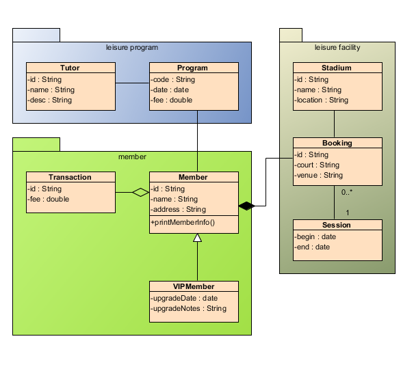
Class Diagram provides an overview of the target system by describing the objects and classes inside the system and the relationships between them. It provides a wide variety of usages; from modeling the domain-specific data structure to detailed design of the target system.
Key Benefits:
-
Domain Modeling: Capture business entities and their relationships
-
System Design: Define software architecture at the class level
-
Code Generation: Generate implementation code from model elements
-
Documentation: Create maintainable technical documentation
-
Model Reuse: Share class models across interaction diagrams for dynamic behavior modeling
-
Automated Generation: Use Form Diagram to generate diagrams automatically with user-defined scope
Core Notations and Elements
Basic Structural Elements
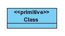
 Class
Class
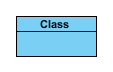
Definition: A class describes a set of objects that share the same specifications of features, constraints, and semantics. Class is a kind of classifier whose features are attributes and operations.
Key Properties:
| Property | Description |
|---|---|
| Name | The name of the class |
| Parent | The model element that owns the class |
| Visibility | Determines namespace appearance and accessibility |
| Abstract | If true, class cannot be instantiated directly |
| Leaf | If true, class cannot be further specialized |
| Root | Indicates whether the class has no ancestors |
| Active | Determines if objects are active (concurrent) or passive |
| Attributes | Direct properties owned by the class |
| Operations | Behavioral features specifying invocation parameters |
| Template Parameters | Formal parameters for template binding |
 Class <>
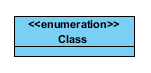
Definition: A form of class that acts as a container of enumeration literals. For instance, an enumeration Color holds enumeration literals red, green, and blue.
 Class <>
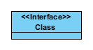
Definition: An interface is a kind of classifier that represents a declaration of a set of coherent public features and obligations. An interface specifies a contract; any instance of a classifier that realizes the interface must fulfill that contract.
Key Characteristics:
-
Interfaces are declarations and not instantiable
-
Implemented by instances of instantiable classifiers
-
A classifier may implement multiple interfaces
-
May include constraints and protocol specifications
 Class <>
Definition: A form of class that represents a predefined data type. For instance, a boolean class (type).
 Note
Note
Definition: A note (comment) gives the ability to attach various remarks to elements. A comment carries no semantic force, but may contain information that is useful to a modeler.
 Constraint
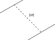
Definition: A condition or restriction expressed in natural language text or in a machine readable language for the purpose of declaring some of the semantics of an element.
Properties:
| Property | Description |
|---|---|
| Name | Optional name of the constraint |
| Expression | The condition that must be true for satisfaction |
| Documentation | Description of the constraint |
 Collaboration
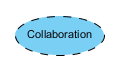
Definition: A collaboration is represented as a kind of classifier and defines a set of cooperating entities to be played by instances (its roles), as well as a set of connectors that define communication paths between the participating instances.
 Model
Model
Definition: A top-level package that contains the entire model or a significant part of it.
 NARY
NARY
Definition: Represents an n-ary association connecting multiple classifiers simultaneously.
Relationship Types
Association Relationships
 Association (Without aggregation)
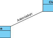
Definition: An association specifies a semantic relationship that can occur between typed instances. It has at least two ends represented by properties, each of which is connected to the type of the end.
Key Properties:
| Property | Description |
|---|---|
| Name | The name of the association |
| Visibility | Namespace appearance and accessibility |
| Association End From/To | Source and target of the association |
| Abstract | If true, association is incomplete and not instantiable |
| Leaf | If true, association cannot be further specialized |
| Derived | Specifies if derived from other model elements |
 Aggregation (Shared association)
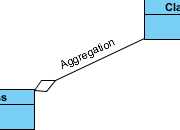
Definition: A kind of association that has one of its end marked shared as a kind of aggregation, meaning that it has a shared aggregation (whole-part relationship where parts can exist independently).
 Composition (Composite association)
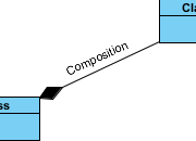
Definition: A strong form of aggregation where a part instance can be included in at most one composite at a time. If a composite is deleted, all of its parts are normally deleted with it.
Key Characteristics:
-
Parts cannot belong to multiple composites simultaneously
-
Deleting the composite typically deletes its parts
-
Parts can be removed before composite deletion
-
Compositions may form directed acyclic graphs with transitive deletion
 Association Class
Definition: A model element that has both association and class properties. An AssociationClass can be seen as an association that also has class properties, or as a class that also has association properties.
Related Resource: Drawing association class
Dependency Relationships
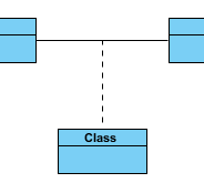
 Dependency
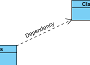
Definition: A relationship that signifies that a single or a set of model elements requires other model elements for their specification or implementation.
Properties:
| Property | Description |
|---|---|
| Supplier | Independent element(s) in the relationship |
| Client | Dependent element(s) in the relationship |
| Visibility | Namespace appearance and accessibility |
| Mapping | Optional expression stating the relationship |
 Abstraction
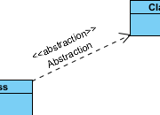
Definition: A relationship that relates two elements or sets of elements that represent the same concept at different levels of abstraction or from different viewpoints.
 Realization
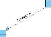
Definition: A specialized abstraction relationship between two sets of model elements, one representing a specification (the supplier) and the other represents an implementation of the latter (the client).
Use Cases: Stepwise refinement, optimizations, transformations, templates, model synthesis, framework composition
 Generalization
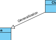
Definition: A taxonomic relationship between a more general classifier and a more specific classifier. Each instance of the specific classifier is also an indirect instance of the general classifier.
Key Property:
| Property | Description |
|---|---|
| Substitutable | If true, specific classifier can replace general classifier at runtime |
 Usage
Usage
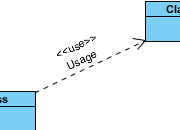
Definition: A relationship in which one element requires another element (or set of elements) for its full implementation or operation.
 Access
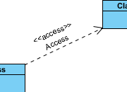
Definition: An element import defined as a directed relationship between an importing namespace and a packageable element. The name of the packageable element or its alias is added to the namespace of the importing namespace.
Notation:
-
<\<import>>keyword for public visibility -
<\<access>>keyword for private visibility
 Import
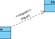
Definition: A package import is defined as a directed relationship that identifies a package whose members are to be imported by a namespace.
 Permission
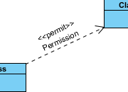
Definition: A kind of dependency that grants a model element permission to access elements in another namespace.
 Instantiation
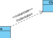
Definition: A usage dependency among classifiers indicating that operations on the client create instances of the supplier.
 Binding
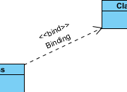
Definition: TemplateBinding is a directed relationship from a bound templateable element to the template signature of the target template. A TemplateBinding owns a set of template parameter substitutions.
 Derive
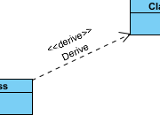
Definition: Specifies a derivation relationship among model elements that are usually, but not necessarily, of the same type. A derived dependency specifies that the client may be computed from the supplier.
 Refine
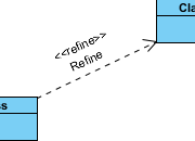
Definition: Specifies a refinement relationship between model elements at different semantic levels, such as analysis and design.
Use Cases: Transformations from analysis to design, model evolution
 Trace
Trace
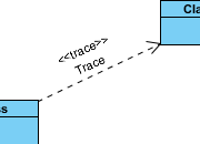
Definition: Specifies a trace relationship between model elements or sets of model elements that represent the same concept in different models.
Primary Use: Tracking requirements and changes across models; mapping is usually informal and bidirectional
 Substitution
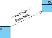
Definition: A relationship between two classifiers which signifies that the substitutingClassifier complies with the contract specified by the contract classifier.
Implication: Instances of the substituting classifier are runtime substitutable where instances of the contract classifier are expected.
 Merge
Merge
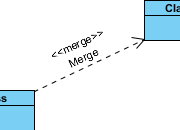
Definition: A package merge is a directed relationship between two packages that indicates that the contents of the two packages are to be combined.
Key Characteristics:
-
Similar to Generalization but for package contents
-
Used when elements in different packages represent the same concept
-
Enables incremental extension of base concepts
-
Particularly useful in meta-modeling and UML metamodel definition
Class Variants and Stereotypes
ORM-Specific Classes
 Class <>
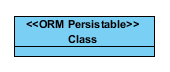
Definition: A special form of class that can be used to model an object model of a relational database. ORM code can be generated from a set of ORM Persistable classes.
Additional Properties:
| Property | Description |
|---|---|
| ORM Class Details | Settings affecting ORM code generation |
| Business Key | Used for generating equals() and hashCode() operations |
| ORM Query | Define ORM Qualifiers and named queries |
 Class <>
Definition: A special form of class that captures common attributes of sub-ORM-Persistable classes.
 Class <>
Definition: A user type class defines an object type for object model that can be accessed in generated ORM code, and persist in database as a column instead of an entity.
Related Resource: Hibernate User Type Support
 Class <>
Definition: An ORM Parameterized type provides you with opportunity to enforce the correctness of data by implementing correctness checking in generated ORM code.
 Class <>
Definition: A special form of class for modeling EJB entity bean.
Additional Properties:
| Property | Description |
|---|---|
| EJB Class Code Details | EJB-related attributes for code generation |
Properties and Configuration
Common Class Properties Reference
| Property | Applies To | Description |
|---|---|---|
| Name | All elements | Identifier for the model element |
| Parent | Classes, Interfaces | Owning model element |
| Visibility | Most elements | Controls namespace appearance: public, private, protected, package |
| Abstract | Classes, Associations | If true, element is incomplete and not directly instantiable |
| Leaf | Classes, Associations | If true, element cannot be further specialized |
| Root | Classes | Indicates whether element has no ancestors |
| Active | Classes | Determines if objects are active (concurrent) or passive |
| Business Model | Classes | Flag to mark as a “business class” |
| Attributes | Classes | Direct properties owned by the class |
| Operations | Classes | Behavioral features with parameters and constraints |
| Template Parameters | Templateable elements | Formal parameters for generic/parameterized elements |
| Derived | Associations | Specifies if element is derived from other model elements |
Code Generation Settings
Java-Specific Configuration
-
Java Annotations: Metadata added to Java source code for annotation purposes
-
Round-trip Engineering: Generate and synchronize Java code
ORM-Specific Configuration
-
ORM Query: Define qualifiers and named queries for persistable classes
-
Business Key: Configure fields used for equals()/hashCode() generation
-
Column Mapping: Specify database column names and types
Related UML Diagram Types
Class diagrams integrate with other UML diagrams for comprehensive system modeling:
| Diagram Type | Purpose | Link |
|---|---|---|
| Use Case Diagram | Capture functional requirements | Use case diagram |
| Sequence Diagram | Model dynamic interactions over time | Sequence diagram |
| Communication Diagram | Show object interactions and links | Communication diagram |
| State Machine Diagram | Model object lifecycle and states | State machine diagram |
| Activity Diagram | Represent workflows and processes | Activity diagram |
| Component Diagram | Show physical software components | Component diagram |
| Deployment Diagram | Model hardware and software deployment | Deployment diagram |
| Package Diagram | Organize model elements into packages | Package diagram |
| Object Diagram | Show instances at a specific moment | Object diagram |
| Composite Structure Diagram | Model internal structure of classifiers | Composite structure diagram |
| Timing Diagram | Focus on timing constraints | Timing diagram |
| Interaction Overview Diagram | Combine interaction and activity diagrams | Interaction overview diagram |
Reference List
- Primary Diagram References
-
Use Case Diagram: Visual representation of system functionality from user perspective, capturing actors and their goals.
-
Sequence Diagram: Shows object interactions arranged in time sequence, emphasizing message ordering.
-
Communication Diagram: Displays object interactions with emphasis on structural relationships between objects.
-
State Machine Diagram: Models the dynamic behavior of an object through its lifecycle states and transitions.
-
Activity Diagram: Represents workflows, business processes, and operational steps with control flow.
-
Component Diagram: Illustrates physical software components, their interfaces, and dependencies.
-
Deployment Diagram: Shows hardware nodes, software artifacts, and their deployment relationships.
-
Package Diagram: Organizes model elements into hierarchical packages for modularity and namespace management.
-
Object Diagram: Displays instances of classes and their links at a specific point in time.
-
Composite Structure Diagram: Models internal structure of classifiers including parts, ports, and connectors.
-
Timing Diagram: Focuses on timing constraints and state changes over precise time intervals.
-
Interaction Overview Diagram: Combines interaction diagrams with activity diagram notation for high-level interaction flow.
- Class Diagram Notation References
-
Abstraction: Relationship relating elements representing same concept at different abstraction levels.
-
Access: Element import relationship controlling visibility of imported packageable elements.
-
Aggregation (Shared association): Whole-part relationship where parts can exist independently of the whole.
-
Association (Without aggregation): Semantic relationship between typed instances with navigable ends.
-
Association Class: Model element combining association and class properties for relationship attributes.
-
Binding: Template binding relationship with parameter substitutions for generic elements.
-
Class: Core classifier describing objects with shared features, attributes, and operations.
-
Class <>: Container class for enumeration literals representing fixed value sets.
-
Class <>: Contract specification declaring public features for implementing classifiers.
-
Class <>: Predefined data type class representing basic language types.
-
Class <>: Database-mapped class supporting ORM code generation and persistence.
-
Class <>: Abstract base class for sharing common ORM attributes across persistable subclasses.
-
Class <>: Custom type persisted as database column rather than entity table.
-
Class <>: Parameterized type enabling data correctness validation in ORM code.
-
Class <>: EJB entity bean modeling class for enterprise Java applications.
-
Collaboration: Classifier defining cooperating roles and communication paths for interacting instances.
-
Composition (Composite association): Strong whole-part relationship with exclusive ownership and cascading deletion.
-
Constraint: Condition or restriction declaring semantics of model elements.
-
Dependency: Relationship indicating one element requires another for specification or implementation.
-
Derive: Relationship specifying client element computable from supplier element.
-
Generalization: Inheritance relationship where specific classifier inherits features from general classifier.
-
Import: Package import relationship making package members available to importing namespace.
-
Instantiation: Dependency indicating client operations create instances of supplier classifier.
-
Merge: Package merge combining contents of two packages for incremental concept extension.
-
Model: Top-level container for organizing model elements and packages.
-
NARY: N-ary association connecting multiple classifiers simultaneously.
-
Note: Comment element for attaching non-semantic remarks to model elements.
-
Permission: Dependency granting access permission to elements in another namespace.
-
Realization: Specialized abstraction where client implements specification defined by supplier.
-
Refine: Relationship between model elements at different semantic levels like analysis and design.
-
Substitution: Relationship indicating substituting classifier complies with contract classifier specification.
-
Trace: Relationship tracking same concept across different models, primarily for requirements management.
-
Usage: Dependency where client element requires supplier element for full implementation or operation.
- Tutorial and Resource References
-
Drawing Association Class: Step-by-step guide for creating association classes in Visual Paradigm.
-
Generate and Synchronize Java Code: Tutorial for round-trip engineering between class diagrams and Java implementation.
-
Hibernate User Type Support: Resource for implementing custom Hibernate user types with ORM-Persistable classes.
- Standards Reference
-
Object Management Group – Unified Modeling Language: Official UML specification source from the standards body governing UML.
-
Definition of notations is quoted from Object Management Group Unified Modeling Language (OMG UML) Superstructure Version 2.2 and former versions (for notations that do not exist anymore in latest specification).
- This guide is based on Visual Paradigm’s UML Class Diagram documentation. For the most current specifications, always refer to the official OMG UML standards.
