


Business Process Model and Notation, or BPMN, is a standardized visual language for representing business processes. It helps business users, analysts, developers, and process owners describe how work is performed, who performs it, what decisions occur, and how information moves between participants.
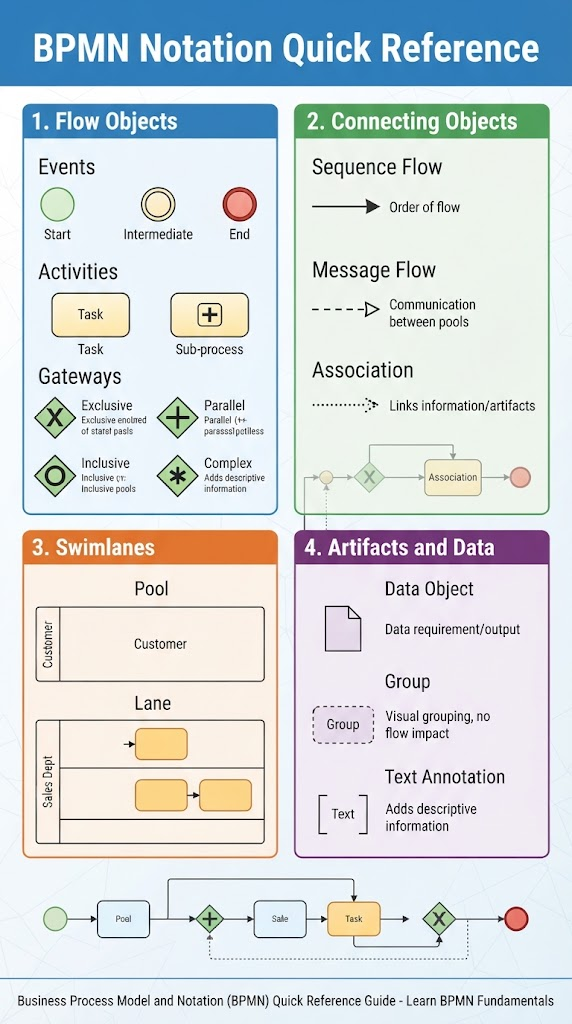
BPMN diagrams are built from four primary categories:
-
Flow objects — the main elements of a process
-
Connecting objects — relationships and movement between elements
-
Swimlanes — participants and areas of responsibility
-
Artifacts and data — supporting information and explanatory elements
1. What BPMN Represents
A BPMN model typically describes:
-
Who performs an activity
-
What work is performed
-
When the process starts and ends
-
What decisions affect the process path
-
How activities are ordered
-
How participants communicate
-
What data or documents are used
-
What events interrupt or trigger work
For example, an order fulfillment process might include:
-
A customer submits an order.
-
The company checks inventory.
-
If the item is available, the order is prepared.
-
If it is unavailable, the customer is notified.
-
Payment is processed.
-
The order is shipped.
-
The process ends.
BPMN provides symbols for each of these steps and relationships.
2. The Four Main BPMN Element Categories
2.1 Flow Objects
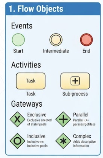
Flow objects define the behavior of the process. They consist of:
-
Events
-
Activities
-
Gateways
These are the central elements in almost every BPMN process diagram.
2.2 Connecting Objects
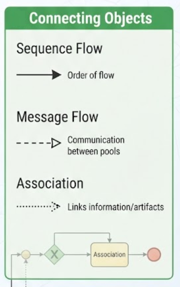
Connecting objects show how flow objects relate to one another. They include:
-
Sequence flows
-
Message flows
-
Associations
2.3 Swimlanes
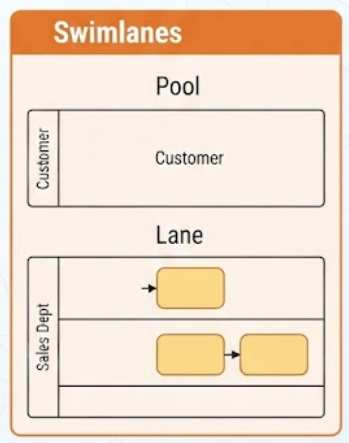
Swimlanes organize process elements according to responsibility. They include:
-
Pools
-
Lanes
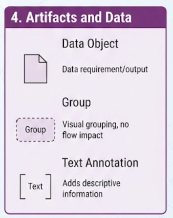
2.4 Artifacts and Data
Artifacts provide additional context without directly controlling the process flow. They include:
-
Data objects
-
Groups
-
Text annotations
3. Events
An event represents something that happens during a process. Events do not usually describe work; instead, they indicate a trigger, a change, an interruption, or a result.
Events are drawn as circles.
3.1 Start Events
A start event indicates where a process begins.
Symbol: Thin-lined circle
Examples:
-
A customer places an order.
-
A scheduled date is reached.
-
An employee submits a request.
-
A message is received.
-
A payment is initiated.
A process generally has at least one start event, although complex models may have several possible starting points.
Common start-event types
-
None start event: The process starts without a specific trigger.
-
Message start event: A message or request starts the process.
-
Timer start event: The process starts at a specified time or interval.
-
Conditional start event: A condition becoming true starts the process.
-
Signal start event: A broadcast signal starts the process.
-
Multiple start event: One of several possible triggers can start the process.
-
Parallel multiple start event: Several triggers must occur before the process starts.
3.2 Intermediate Events
An intermediate event occurs between the start and end of a process.
Symbol: Double-lined circle
Intermediate events may:
-
Wait for something to happen
-
Send or receive information
-
Delay the process
-
Interrupt an activity
-
Catch an error
-
Trigger another action
-
Mark a business milestone
Examples:
-
Wait seven days for a payment.
-
Receive approval from a manager.
-
Send a confirmation email.
-
Catch an error during processing.
-
Wait for a shipment notification.
Intermediate events can be attached directly to the boundary of an activity. These are called boundary events and are commonly used for exceptions, timeouts, and cancellations.
3.3 End Events
An end event indicates that a particular process path has finished.
Symbol: Thick-lined circle
Examples:
-
Order completed
-
Request rejected
-
Customer notified
-
Payment failed
-
Process canceled
A process may have multiple end events because different paths may terminate in different results.
Common end-event types
-
None end event: The path ends without a special result.
-
Message end event: A message is sent when the path ends.
-
Error end event: An error is generated.
-
Escalation end event: An escalation is raised.
-
Terminate end event: The entire process instance is immediately terminated.
-
Cancel end event: A transaction is canceled.
-
Signal end event: A signal is broadcast.
-
Multiple end event: Several results occur together.
4. Activities
An activity represents work performed within a process. Activities are shown as rounded rectangles.
There are two main types:
-
Tasks
-
Subprocesses
4.1 Tasks
A task is a single unit of work that is not broken down further within the current diagram.
Examples:
-
Verify customer identity
-
Review application
-
Calculate invoice
-
Send email
-
Approve request
-
Pack shipment
A task should normally be labeled with a short verb-object phrase, such as:
-
“Validate payment”
-
“Create invoice”
-
“Review application”
Avoid vague labels such as “Processing” or “Handle request.”
4.2 Task Types
BPMN provides several specialized task types.
User task
A person performs the task with the assistance of a software application.
Examples:
-
Review claim
-
Approve purchase
-
Enter customer details
Manual task
A person performs the task without the use of a process execution system.
Examples:
-
Inspect physical equipment
-
Deliver package
-
Sign paper form
Service task
A software service or automated application performs the task.
Examples:
-
Calculate tax
-
Check credit score
-
Update customer database
Script task
A script executes within the process engine.
Examples:
-
Transform data
-
Calculate a value
-
Format a message
Business rule task
A business rule or decision service determines a result.
Examples:
-
Determine eligibility
-
Calculate risk category
-
Apply discount policy
Send task
The task sends a message to another participant.
Examples:
-
Send order confirmation
-
Send approval request
-
Send shipping notice
Receive task
The task waits for a message from another participant.
Examples:
-
Receive customer response
-
Receive payment confirmation
-
Receive delivery notice
4.3 Subprocesses
A subprocess represents a collection of activities grouped into a larger activity.
A subprocess may be:
-
Collapsed: Shown as a single activity with a plus sign
-
Expanded: Its internal steps are shown directly in the diagram
For example, “Process loan application” might contain:
-
Collect documentation
-
Verify applicant information
-
Perform credit assessment
-
Review risk
-
Issue decision
Subprocesses are useful for:
-
Simplifying a high-level diagram
-
Reusing a common process
-
Organizing complex work
-
Showing different levels of detail
-
Separating major phases of a process
Embedded and reusable subprocesses
An embedded subprocess belongs to its parent process.
A call activity invokes a reusable global process that may be used in multiple places. For example, “Perform identity verification” might be reused by account opening, loan processing, and payment setup.
5. Gateways
A gateway controls how the process diverges or converges. Gateways are shown as diamond-shaped symbols.
They are used for:
-
Making decisions
-
Splitting the process into paths
-
Synchronizing parallel paths
-
Merging alternative paths
A gateway does not perform work itself. It controls the flow of work.
5.1 Exclusive Gateway
An exclusive gateway, often called an XOR gateway, selects exactly one outgoing path.
Typical symbol: Diamond containing an “X”
Example:
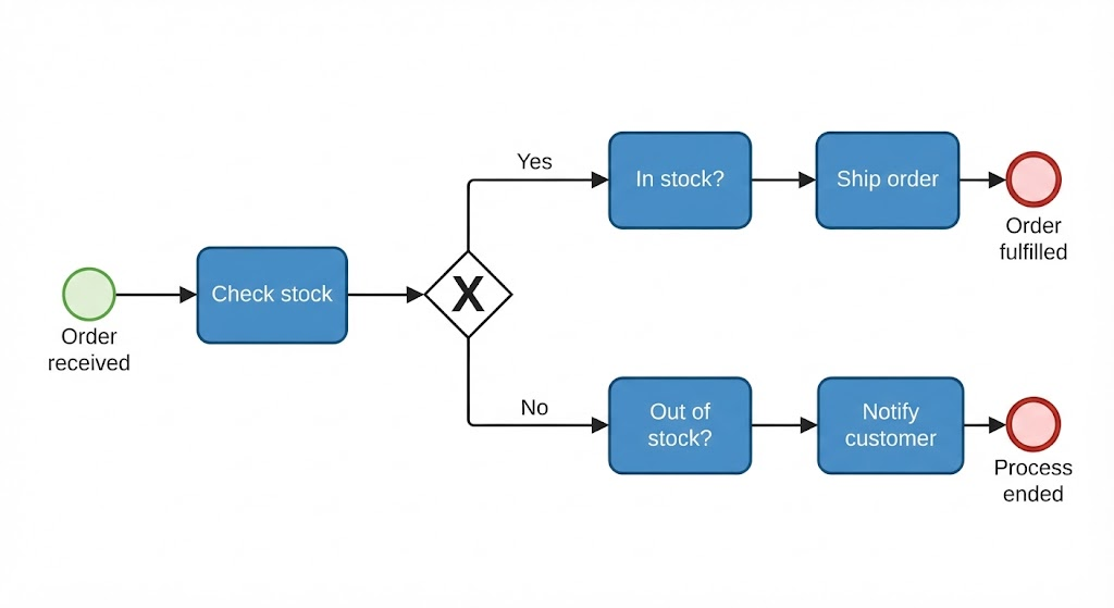
Only one path is taken.
Typical use cases:
-
If payment is approved, continue; otherwise reject.
-
If the customer is local, use local delivery; otherwise use international shipping.
-
If the application is complete, proceed; otherwise request missing information.
Important rule
Conditions should be clear and mutually exclusive whenever possible. The model should also define what happens if no condition is true, typically using a default flow.
5.2 Parallel Gateway
A parallel gateway, or AND gateway, splits the process into multiple paths that occur simultaneously.
Typical symbol: Diamond containing a plus sign
Example:
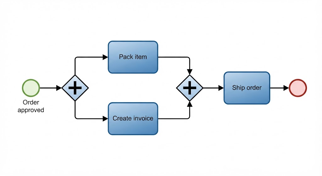
Both activities must be completed before the process continues after the joining gateway.
Typical use cases:
-
Notify the customer and update the database
-
Perform credit and identity checks simultaneously
-
Prepare documentation while scheduling delivery
Parallel split
Creates multiple concurrent paths.
Parallel join
Waits until all incoming paths have completed.
5.3 Inclusive Gateway
An inclusive gateway, or OR gateway, activates one or more paths depending on conditions.
Typical symbol: Diamond containing a circle
Example:
A customer may qualify for:
-
A discount
-
Free shipping
-
A loyalty reward
One, two, or all three paths could be activated.
Unlike an exclusive gateway, an inclusive gateway can select multiple outgoing paths. The corresponding joining gateway waits for the paths that were actually activated.
5.4 Complex Gateway
A complex gateway is used for sophisticated synchronization or decision rules that cannot be represented easily with exclusive, parallel, or inclusive gateways.
Typical symbol: Diamond containing an asterisk
Examples:
-
Continue when any two of three approvals are received.
-
Continue when a minimum number of required checks are complete.
-
Start a special escalation path when a combination of conditions occurs.
Complex gateways should be used sparingly because they can make diagrams harder to understand and execute.
5.5 Event-Based Gateway
An event-based gateway chooses a path based on which event happens first.
Example:
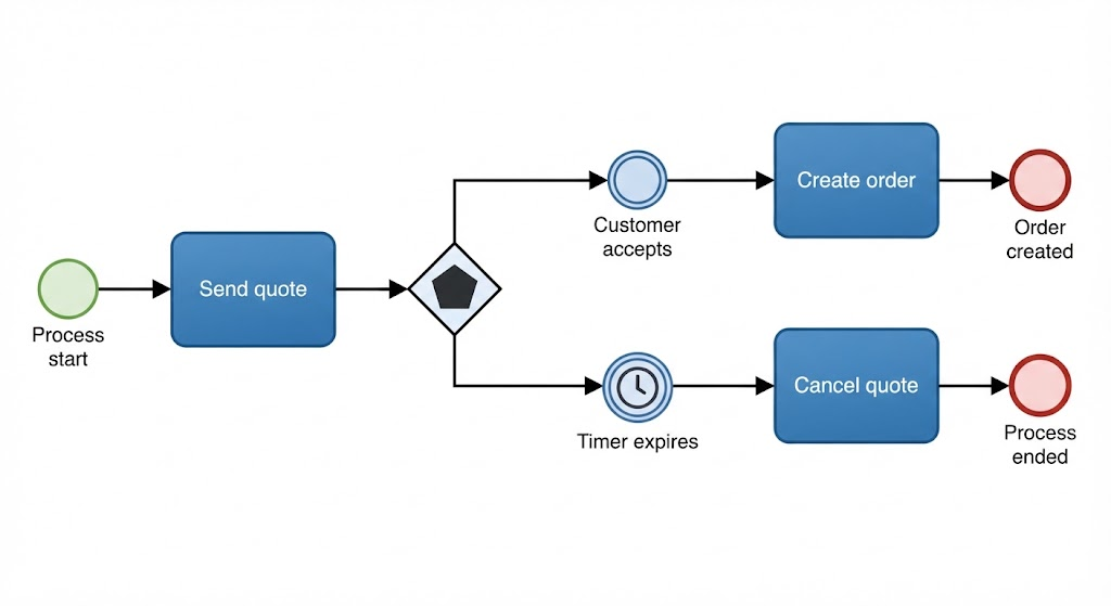
The process does not evaluate ordinary data conditions. Instead, it waits for events.
Common uses:
-
Wait for approval or timeout
-
Wait for a customer response or cancellation
-
Wait for a payment or payment deadline
6. Connecting Objects
Connecting objects show how activities, events, gateways, and participants are related.
6.1 Sequence Flow
A sequence flow shows the order in which activities and events occur within a process.
Symbol: Solid line with a filled arrowhead
Example:
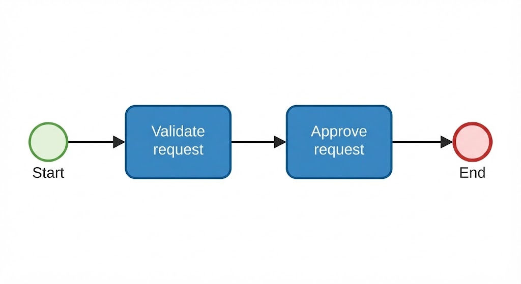
Sequence flows may include conditions, especially when leaving a gateway.
Rules for sequence flow
-
Sequence flow is used within a pool.
-
It shows the order of execution.
-
It should generally move in a consistent direction, usually left to right.
-
It must not cross pool boundaries.
-
Conditional flows should have clear labels.
A sequence flow may be marked as the default flow, indicating the path taken when no other condition applies.
6.2 Message Flow
A message flow shows communication between separate participants, usually different pools.
Symbol: Dashed line with an open arrowhead
Examples:
-
Customer sends order to supplier.
-
Bank sends payment confirmation to merchant.
-
Supplier sends shipping notice to customer.
Message flow represents communication, not the internal order of activities.
Key distinction
-
Sequence flow: What happens next within a participant’s process
-
Message flow: Communication between participants
A message flow should not be used to connect activities inside the same pool.
6.3 Association
An association links an artifact or piece of information to a flow object.
Symbol: Dotted or dashed line, usually without an arrowhead
Examples:
-
Attach a data object to a task.
-
Link an explanatory annotation to an activity.
-
Show that a document is an input or output.
Associations add context but do not control process execution.
7. Swimlanes
Swimlanes organize process elements by participant, role, department, system, or responsibility.
They make it easier to answer:
-
Who performs this task?
-
Which department owns this activity?
-
Which system is involved?
-
Where does communication cross organizational boundaries?
The two main swimlane types are pools and lanes.
7.1 Pools
A pool represents a participant in a process.
A participant may be:
-
An organization
-
A company
-
A customer
-
A supplier
-
A government agency
-
A software system
-
An independent business entity
Example pools:
-
Customer
-
Retailer
-
Bank
-
Shipping company
Each pool may contain its own process flow. Message flows connect separate pools.
Black-box pool
A pool can be shown as a black-box participant when its internal process is not modeled.
For example, a company may model its interaction with a bank without showing the bank’s internal activities.
The bank is represented as a pool with a name but no internal flow.
Pool boundary
Sequence flows should remain inside their pool. Communication across pools should be represented with message flows.
7.2 Lanes
A lane is a subdivision within a pool.
Lanes may represent:
-
Departments
-
Job roles
-
Teams
-
Systems
-
Locations
-
Areas of responsibility
Example:
Pool: Retailer
 ├── Sales
 ├── Finance
 ├── Warehouse
 └── Customer Service
Tasks are placed in the lane of the person, department, or system responsible for performing them.
Lane design considerations
Lanes can represent either:
-
Organizational responsibility, such as Sales or Finance
-
Functional responsibility, such as Manual Work or Automated System
Use one consistent interpretation within a diagram.
8. Artifacts and Data
Artifacts provide additional information about the process. They do not normally determine the order of execution.
8.1 Data Objects
A data object represents information that is created, used, modified, or produced by activities.
Examples:
-
Customer order
-
Application form
-
Invoice
-
Contract
-
Shipping label
-
Approval record
-
Payment confirmation
A data object can show whether data is:
-
An input to an activity
-
An output from an activity
-
Updated by an activity
-
Passed between activities
For example:
Application form → Review application → Approved application
Data objects help answer:
-
What information is required?
-
What information is produced?
-
What document is being transformed?
-
Which activity uses a particular record?
Data store
A data store represents information that persists beyond the current process instance.
Examples:
-
Customer database
-
Document repository
-
Inventory system
-
Employee records
A data object is typically associated with work in the process, while a data store represents a persistent repository.
8.2 Groups
A group visually organizes related elements.
Symbol: Dashed rounded rectangle
Groups may be used to show:
-
A project phase
-
A compliance category
-
A related set of activities
-
A logical region of the process
Groups do not affect process execution and should not be confused with subprocesses.
8.3 Text Annotations
A text annotation adds explanatory information to a diagram.
Examples:
-
“Requires manager approval”
-
“Customer must respond within five business days”
-
“This step is automated”
-
“The system retries the operation three times”
Annotations are connected to relevant elements using associations.
9. Common BPMN Event Types
BPMN events can be categorized by what triggers or results from them.
Message events
Represent the sending or receiving of messages.
Examples:
-
Receive an order
-
Send an approval request
-
Receive a payment notification
Timer events
Represent time-based conditions.
Examples:
-
Wait 24 hours
-
Start every Monday
-
Escalate if no response is received within five days
Error events
Represent errors or failures.
Examples:
-
Payment service unavailable
-
Invalid customer information
-
Document processing failure
Escalation events
Represent a business escalation that does not necessarily indicate a technical failure.
Examples:
-
Escalate overdue case
-
Request supervisor review
-
Notify management of a high-risk transaction
Conditional events
Trigger when a business condition becomes true.
Examples:
-
Inventory falls below the reorder threshold
-
Customer balance exceeds the limit
-
Required documents are complete
Signal events
Represent a broadcast communication that may be received by multiple processes.
Examples:
-
Emergency closure announced
-
Policy updated
-
Market alert issued
Cancel events
Used mainly within transactional subprocesses to indicate cancellation.
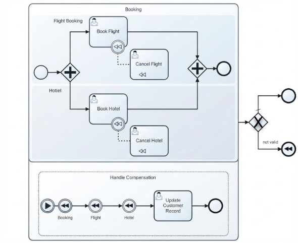
Compensation events
Used to reverse or compensate for work that has already occurred.
Example:
-
Cancel a payment after an order is rejected
-
Refund a customer after a service is canceled
Link events
Connect distant parts of a process diagram without drawing long sequence-flow lines. They are useful in large diagrams but should not replace clear process structure unnecessarily.
Multiple events
Represent multiple possible triggers or results.
10. Boundary Events
A boundary event is attached to the edge of an activity or subprocess. It represents something that occurs while that activity is in progress.
Example:
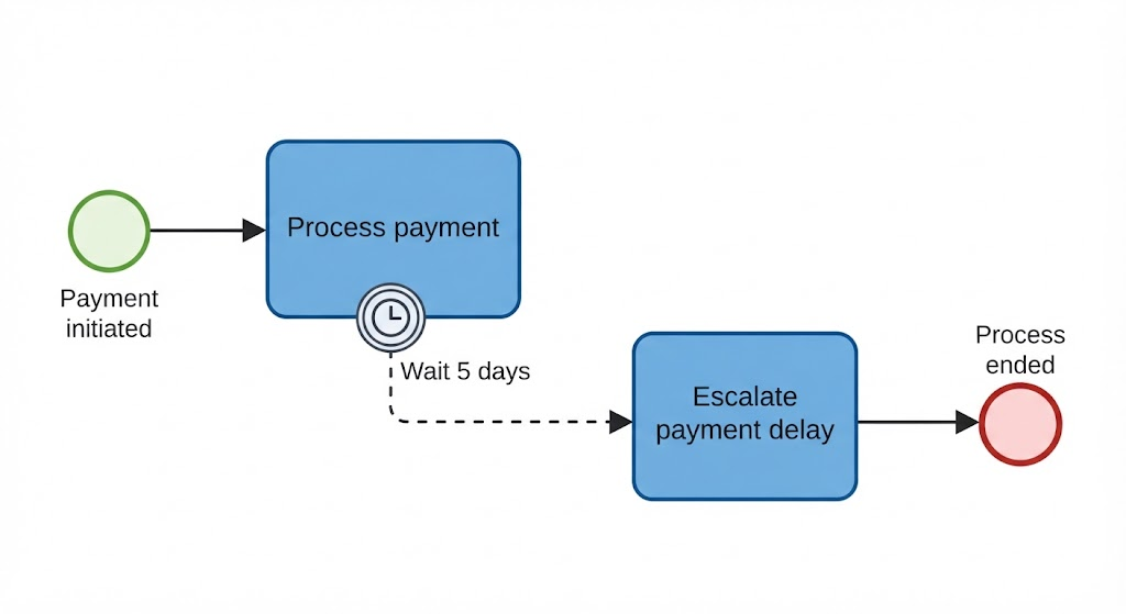
Boundary events are useful for handling exceptions and time constraints.
Interrupting boundary event
The event stops the attached activity when it occurs.
Example:
-
Stop processing when a cancellation request is received.
Non-interrupting boundary event
The event starts an additional path while the attached activity continues.
Example:
-
Send a reminder after three days while continuing to wait for approval.
Common boundary-event uses include:
-
Timeouts
-
Errors
-
Cancellations
-
Escalations
-
Compensation
-
Messages
-
Conditional triggers
11. Transactions and Compensation
Transactions
A transaction is a subprocess in which all activities should succeed together, or the transaction should be canceled or rolled back.
Examples:
-
Booking travel services
-
Completing a payment
-
Reserving inventory
-
Purchasing an insurance policy
A transaction may include a cancel path and compensation behavior.
Compensation
Compensation does not necessarily undo an activity technically. Instead, it performs a business action that offsets the original action.
Examples:
-
Refund a completed payment
-
Cancel a reservation
-
Reverse a shipment
-
Restore an account balance
Compensation is especially useful when a process cannot literally roll back a completed action.
12. BPMN Process Levels
BPMN diagrams are often created at different levels of detail.
Level 1: Descriptive model
Used for communication with business stakeholders.
It typically includes:
-
Start and end events
-
Basic tasks
-
Simple gateways
-
Pools and lanes
-
Main sequence flows
Level 2: Analytical model
Adds more process detail.
It may include:
-
Event types
-
Message flows
-
Boundary events
-
Data objects
-
Exceptions
-
Subprocesses
-
More detailed gateway logic
Level 3: Executable model
Designed for implementation in a workflow or process engine.
It may require:
-
Precise event behavior
-
Automated service tasks
-
Data mappings
-
Technical message definitions
-
Exception handling
-
Timer configuration
-
Variables and expressions
-
Implementation details
A useful practice is to begin with a high-level model and add detail progressively.
13. A Worked Example
Consider a customer order process.
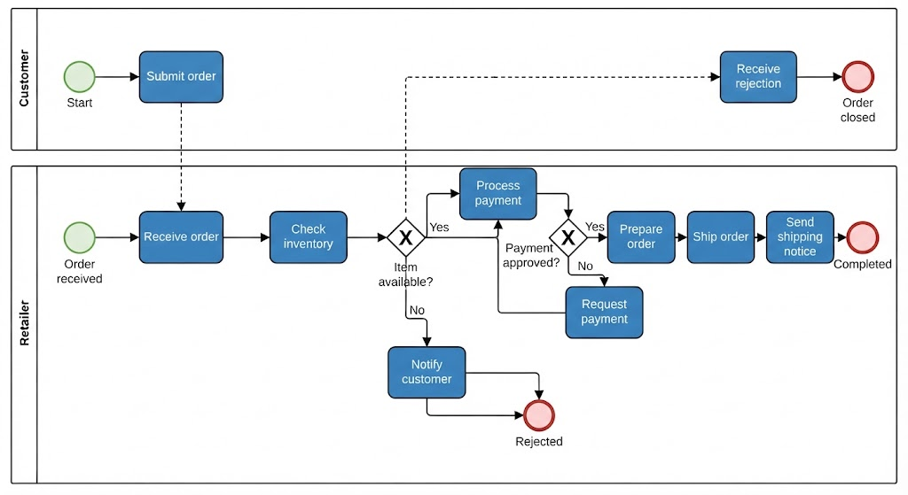
This example illustrates:
-
A start event
-
Tasks
-
A message flow between customer and retailer
-
A sequence flow inside the retailer pool
-
An exclusive gateway
-
Alternative outcomes
-
A payment decision
-
Multiple end events
A more detailed version could include:
-
A timer boundary event for delayed payment
-
A parallel gateway to prepare the order and create the invoice simultaneously
-
Data objects such as Order, Invoice, and Shipping Label
-
Lanes for Sales, Finance, and Warehouse
14. BPMN Modeling Rules and Best Practices
Use clear labels
Name tasks with an action and an object:
-
“Approve application”
-
“Validate address”
-
“Send invoice”
Name gateways as questions when appropriate:
-
“Is payment approved?”
-
“Is documentation complete?”
-
“Is inventory available?”
Keep the main flow readable
Most diagrams are easier to understand when the primary direction is left to right or top to bottom.
Avoid unnecessary:
-
Line crossings
-
Long backward flows
-
Diagonal connectors
-
Excessive gateways
-
Overlapping labels
Use one meaning per symbol
Do not use a gateway merely as a decorative shape. Each gateway should have a clear decision or synchronization purpose.
Distinguish sequence flow from message flow
This is one of the most important BPMN rules:
-
Use sequence flow inside a pool.
-
Use message flow between pools.
-
Do not use sequence flow across pool boundaries.
Model responsibility explicitly
Use lanes when the owner of an activity matters. A process should make it clear whether work is performed by:
-
A person
-
A department
-
An external organization
-
An automated system
Avoid overusing lanes
Too many lanes can make a diagram difficult to read. Use lanes only when responsibility is relevant to understanding or improving the process.
Avoid using annotations as process logic
A text annotation can explain a rule, but it should not replace an actual gateway, event, or task when the rule affects execution.
Use subprocesses to control complexity
If a process contains many detailed steps, group them into subprocesses and create separate diagrams for the details.
Define gateway behavior clearly
For each decision gateway, specify:
-
The conditions for each outgoing path
-
Whether paths are mutually exclusive
-
Whether multiple paths may be activated
-
What happens if no condition is satisfied
-
Whether a joining gateway is required
Use default flows
A default flow provides a defined outcome when no other condition evaluates to true.
This is especially important for exclusive and inclusive gateways.
Label message flows
Message flows should clearly identify the message being exchanged:
-
Order request
-
Payment confirmation
-
Approval response
-
Shipping notification
Model exceptions deliberately
Real processes contain:
-
Timeouts
-
Rejections
-
Errors
-
Cancellations
-
Missing information
-
Escalations
Use boundary events, alternative paths, and error events to represent these situations rather than hiding them in annotations.
15. Common BPMN Mistakes
Treating a gateway as an activity
A gateway controls flow but does not perform work. Use a task for work such as “Evaluate application,” and a gateway for the resulting decision.
Using message flow inside one pool
Message flow represents communication between separate participants. Internal process movement should use sequence flow.
Connecting pools with sequence flow
Sequence flow cannot cross pool boundaries. Use message flow between pools.
Omitting start or end events
Although some diagrams may rely on implicit starts or ends, explicit events make the process easier to understand and execute.
Mixing decision and synchronization logic
A gateway may split paths, merge paths, or do both, but the model should make its purpose clear. Avoid confusing combinations unless they are well-defined.
Using an exclusive gateway where multiple paths are possible
If two or more conditions may be true at the same time, use an inclusive gateway or another appropriate structure.
Creating dead ends
Every meaningful path should lead to another activity, an event, or an end event.
Leaving conditions undefined
A diagram should explain why a path is selected. Conditions such as “Yes,” “No,” “High,” or “Low” should be connected to a clearly defined question or rule.
Modeling every technical detail too early
Start with the business process. Add implementation details only when the model is intended for execution or technical design.
Making one diagram too large
A single diagram that contains every exception, data element, role, and system can become unreadable. Use multiple levels of detail.
16. A Practical BPMN Modeling Method
Step 1: Define the process scope
Identify:
-
Where the process starts
-
Where it ends
-
What is included
-
What is outside the scope
-
Who owns the process
Example scope:
From receipt of a customer order to shipment confirmation.
Step 2: Identify participants
List the people, departments, organizations, and systems involved.
Possible participants:
-
Customer
-
Sales department
-
Finance department
-
Warehouse
-
Payment provider
-
Shipping company
Step 3: Identify the main activities
Write down the major actions in chronological order.
For example:
-
Receive order
-
Validate order
-
Check inventory
-
Process payment
-
Prepare shipment
-
Ship order
-
Notify customer
Step 4: Add start and end events
Identify the event that initiates the process and the possible outcomes.
Step 5: Add gateways
Mark where the process:
-
Makes a decision
-
Splits into parallel work
-
Waits for one of several events
-
Joins previously separated paths
Step 6: Assign responsibilities
Place activities in the appropriate lanes or pools.
Step 7: Add communication
Use message flows to show interactions between independent participants.
Step 8: Add data and exceptions
Represent important documents, records, timeouts, errors, cancellations, and escalations.
Step 9: Validate the diagram
Check that:
-
Every process path has a logical start and end.
-
Sequence flows remain within pools.
-
Message flows connect participants.
-
Gateway conditions are clear.
-
Parallel paths are properly joined.
-
Responsibilities are unambiguous.
-
The diagram can be understood by its intended audience.
17. BPMN Element Quick Reference
| Category | Element | Main purpose |
|---|---|---|
| Flow object | Start event | Shows how a process begins |
| Flow object | Intermediate event | Shows something occurring during the process |
| Flow object | End event | Shows how a process path finishes |
| Flow object | Task | Represents a single unit of work |
| Flow object | Subprocess | Groups related activities |
| Flow object | Exclusive gateway | Selects one path |
| Flow object | Parallel gateway | Activates or synchronizes all paths |
| Flow object | Inclusive gateway | Activates one or more paths |
| Flow object | Complex gateway | Handles advanced conditions |
| Flow object | Event-based gateway | Selects the event that occurs first |
| Connecting object | Sequence flow | Shows order within a process |
| Connecting object | Message flow | Shows communication between participants |
| Connecting object | Association | Links supporting information to process elements |
| Swimlane | Pool | Represents a participant |
| Swimlane | Lane | Organizes responsibility within a pool |
| Artifact | Data object | Represents process information |
| Artifact | Data store | Represents persistent information |
| Artifact | Group | Visually groups elements |
| Artifact | Text annotation | Adds explanatory text |
18. The Most Important BPMN Distinctions
Event versus activity
-
An event is something that happens.
-
An activity is something that is done.
Gateway versus activity
-
A gateway controls the path.
-
An activity performs work.
Sequence flow versus message flow
-
Sequence flow shows internal order.
-
Message flow shows communication between participants.
Pool versus lane
-
A pool represents an independent participant.
-
A lane divides responsibility inside a participant.
Data object versus annotation
-
A data object represents information used or produced by the process.
-
An annotation explains the process but does not represent process data.
Subprocess versus group
-
A subprocess contains executable process behavior.
-
A group only visually organizes elements.
19. Summary
BPMN provides a structured way to model business processes using a small set of recognizable elements:
-
Events show when something starts, happens, or ends.
-
Activities show work being performed.
-
Gateways control decisions, parallel work, and synchronization.
-
Sequence flows show the order of work.
-
Message flows show communication between participants.
-
Pools and lanes identify responsibility.
-
Data objects, groups, and annotations add supporting context.
A strong BPMN diagram is clear about process scope, responsibilities, decisions, communications, data, and exceptions. It uses the simplest element that accurately represents the behavior and avoids unnecessary detail until that detail is needed.
BPMN Reference
- Introducing Visual Paradigm: Your Gateway to Transforming Business Processes: An overview of Visual Paradigm’s BPMN capabilities, including process animation, simulation, RACI/CRUD charts, and sub-process drill-down features.
- BPMN Essentials: Building Clear Business Process Models with Visual Paradigm: A comprehensive guide covering core BPMN elements—flow objects, connectors, artifacts, and swimlanes—with practical e-commerce examples.
- BPMN Modeling Best Practices: A Comprehensive Guide: Covers 22 best practices including reusable process consistency, visual standards, validation levels, stakeholder reviews, and current-state vs. future-state comparison.
- Modeling BPMN Diagrams with Visual Paradigm Desktop: Step-by-step instructions for creating BPMN Business Process Diagrams, including diagram setup, swimlanes, Resource Catalog connections, and validation.
- Getting Started with BPMN Modeling in Visual Paradigm Desktop: A beginner-friendly hands-on guide taking you from blank canvas to fully connected process map using drag-and-drop.
- Tool Usage, Validation, and Repository Issues: Addresses common modeling pitfalls including ignoring validation, not reusing elements, mismanaging versions, and weak integration between BPMN and other models.
- How to Create BPMN Business Process Diagrams in Visual Paradigm: Covers the full workflow from creating a new diagram through process simulation and animation, with detailed steps for pools, lanes, and gateways.
- Mastering BPMN Pools and Lanes: A Practitioner’s Hands-On Guide with Visual Paradigm: Real-world insights on pool orientation, black box pools, manual resizing, nested lanes, and practical workflow hacks from an experienced modeler.
- How to Draw BPMN Diagram?: A practical tutorial demonstrating order fulfillment process modeling with start events, tasks, gateways, sub-processes, and error/escalation intermediate events.
- Process Mapping Made Easy: A concise four-step guide to creating process maps in Visual Paradigm, from starting the tool to finishing with an end event.



 English
 Arabic
 Chinese (Simplified)
 Dutch
Dutch French
 German
 Italian
 Japanese
 Korean
 Portuguese
 Russian
 Spanish