


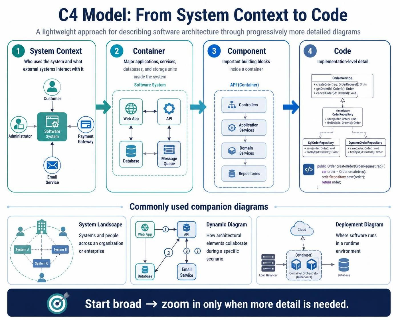
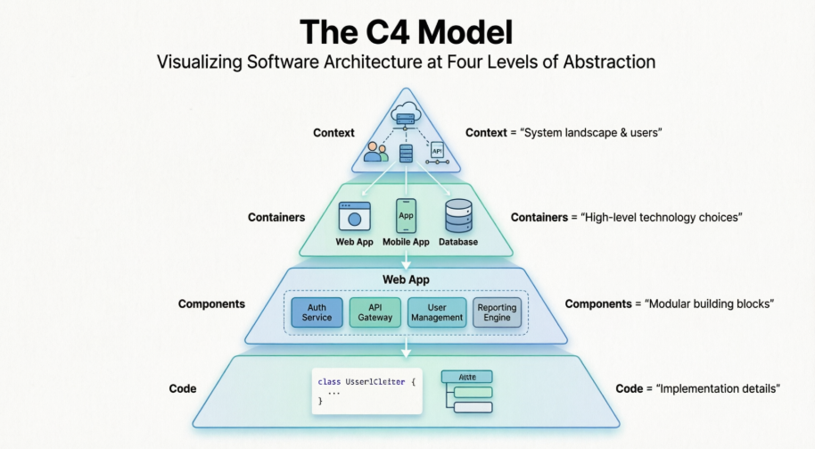
The C4 model is a lightweight approach for describing software architecture through progressively more detailed diagrams:
-
System Context — who uses the system and which external systems interact with it.
-
Container — the major applications, services, databases, and storage units inside the system.
-
Component — the important building blocks inside a container.
-
Code — implementation-level detail, usually represented with UML class or code-generated diagrams.
C4 also commonly uses:
-
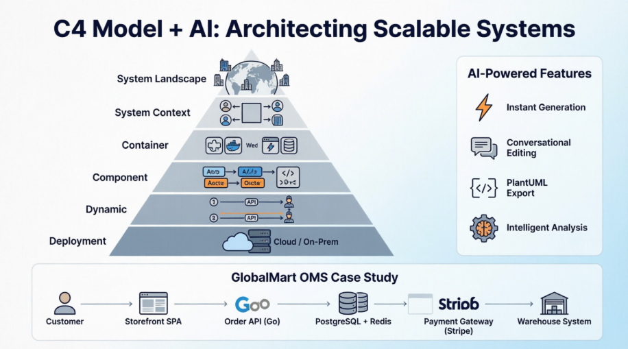
System Landscape — systems and people across an organization or enterprise.
-
Dynamic Diagram — how architectural elements collaborate during a specific scenario.
-
Deployment Diagram — where software runs in a runtime environment.
This guide uses an e-commerce order-processing platform as an example.
1. Tooling Strategy
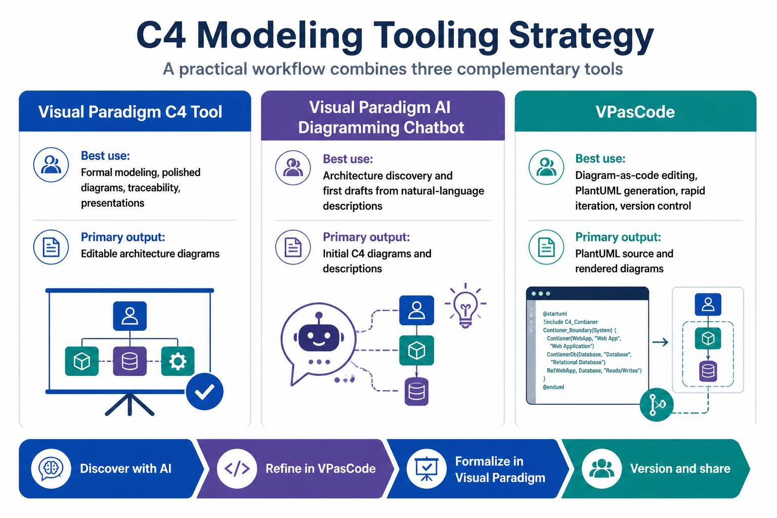
A practical workflow combines three tools:
| Tool | Best use | Primary output |
|---|---|---|
| Visual Paradigm C4 Tool | Formal modeling, polished diagrams, traceability, presentations | Editable architecture diagrams |
| Visual Paradigm AI Diagramming Chatbot | Architecture discovery and first drafts from natural-language descriptions | Initial C4 diagrams and descriptions |
| VPasCode | Diagram-as-code editing, PlantUML generation, rapid iteration, version control | PlantUML source and rendered diagrams |
VPasCode supports PlantUML C4 models and provides a browser-based editor with live rendering. It also supports AI diagram generation, syntax correction, diagram modification, and export to common formats. <citation src="2,5"></citation>
A recommended division of responsibility is:
-
Use the AI Chatbot to explore an architecture.
-
Use VPasCode to generate and refine PlantUML.
-
Use Visual Paradigm C4 Tool for the formal, presentation-ready model.
-
Store the PlantUML source in version control.
-
Review the diagrams with developers, operations, security, and business stakeholders.
Visual Paradigm’s current AI C4 functionality supports System Context, Container, Component, Deployment, System Landscape, and Dynamic diagrams. <citation src="3"></citation>
2. C4 Modeling Principles
Start with the purpose
Every diagram should answer a specific question.
Examples:
-
System Context: What is the system, who uses it, and what does it depend on?
-
Container: What are the major deployable or independently useful parts?
-
Component: How is a particular container internally organized?
-
Dynamic: How do components collaborate in a specific use case?
-
Deployment: Where do the containers run?
Use meaningful abstractions
A C4 element should have:
-
A clear name
-
A concise description
-
A defined responsibility
-
A technology or implementation detail where useful
-
Relationships that describe communication or dependency
Avoid diagrams that contain every class, method, queue, table, and configuration item. C4 is primarily an architecture communication model, not an exhaustive inventory.
Label relationships precisely
A relationship should explain:
-
What communicates with what
-
Why the communication occurs
-
Which protocol or technology is used
-
Whether the interaction is synchronous or asynchronous
Good relationship labels include:
-
Places orders via HTTPS -
Publishes OrderPlaced events -
Reads product data through REST API -
Stores order data in PostgreSQL -
Authenticates users using OAuth 2.0
3. Example System
The example is an Order Processing System with:
-
Customers who place and track orders
-
Administrators who manage products and orders
-
A web application
-
An order API
-
An order-processing service
-
A product catalog service
-
A PostgreSQL database
-
A message broker
-
A payment gateway
-
An email notification service
The system boundary is the software owned by the organization. Payment, email, and identity services are external dependencies.
4. Level 1: System Context Diagram
A System Context diagram shows the system as a single box surrounded by its users and external systems.
When to use it
Use this level for:
-
Executive communication
-
Project onboarding
-
System ownership discussions
-
Scope definition
-
Dependency discovery
-
Security and integration reviews
C4-PlantUML example
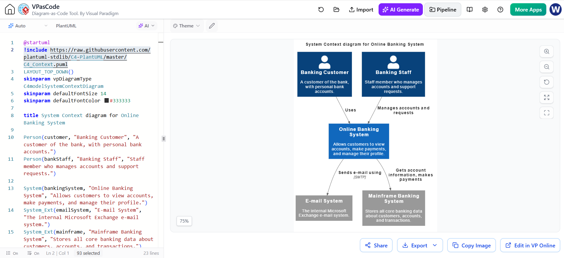
@startuml C4_SystemContext
!include https://raw.githubusercontent.com/plantuml-stdlib/C4-PlantUML/master/C4_Context.puml

LAYOUT_LEFT_RIGHT()
skinparam vpDiagramType C4modelSystemContextDiagram

title System Context - Order Processing Platform

Person(customer, "Customer", "Places orders and tracks delivery status")
Person(admin, "Operations Administrator", "Manages products, orders, refunds, and reports")

System(orderSystem, "Order Processing Platform", "Manages product browsing, checkout, payment authorization, order fulfillment, and notifications")

System_Ext(identity, "Identity Provider", "Authenticates customers and administrators using OAuth 2.0")
System_Ext(payment, "Payment Gateway", "Authorizes and captures card payments")
System_Ext(email, "Email Service", "Sends order confirmations and status notifications")
System_Ext(shipping, "Shipping Provider", "Provides shipment creation and tracking")

Rel(customer, orderSystem, "Browses products, places orders, and tracks shipments", "HTTPS")
Rel(admin, orderSystem, "Manages products, orders, refunds, and reports", "HTTPS")
Rel(orderSystem, identity, "Authenticates users", "OAuth 2.0 / OIDC")
Rel(orderSystem, payment, "Authorizes and captures payments", "HTTPS/REST")
Rel(orderSystem, email, "Sends transactional notifications", "HTTPS/API")
Rel(orderSystem, shipping, "Creates shipments and retrieves tracking information", "HTTPS/REST")

@enduml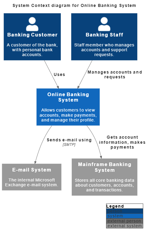
Review questions
Before approving this diagram, ask:
-
Is the system boundary correct?
-
Are all important user roles represented?
-
Are external systems clearly separated?
-
Does every integration have an owner?
-
Are any external dependencies missing?
-
Are the relationship descriptions understandable to a non-developer?
5. Level 2: Container Diagram
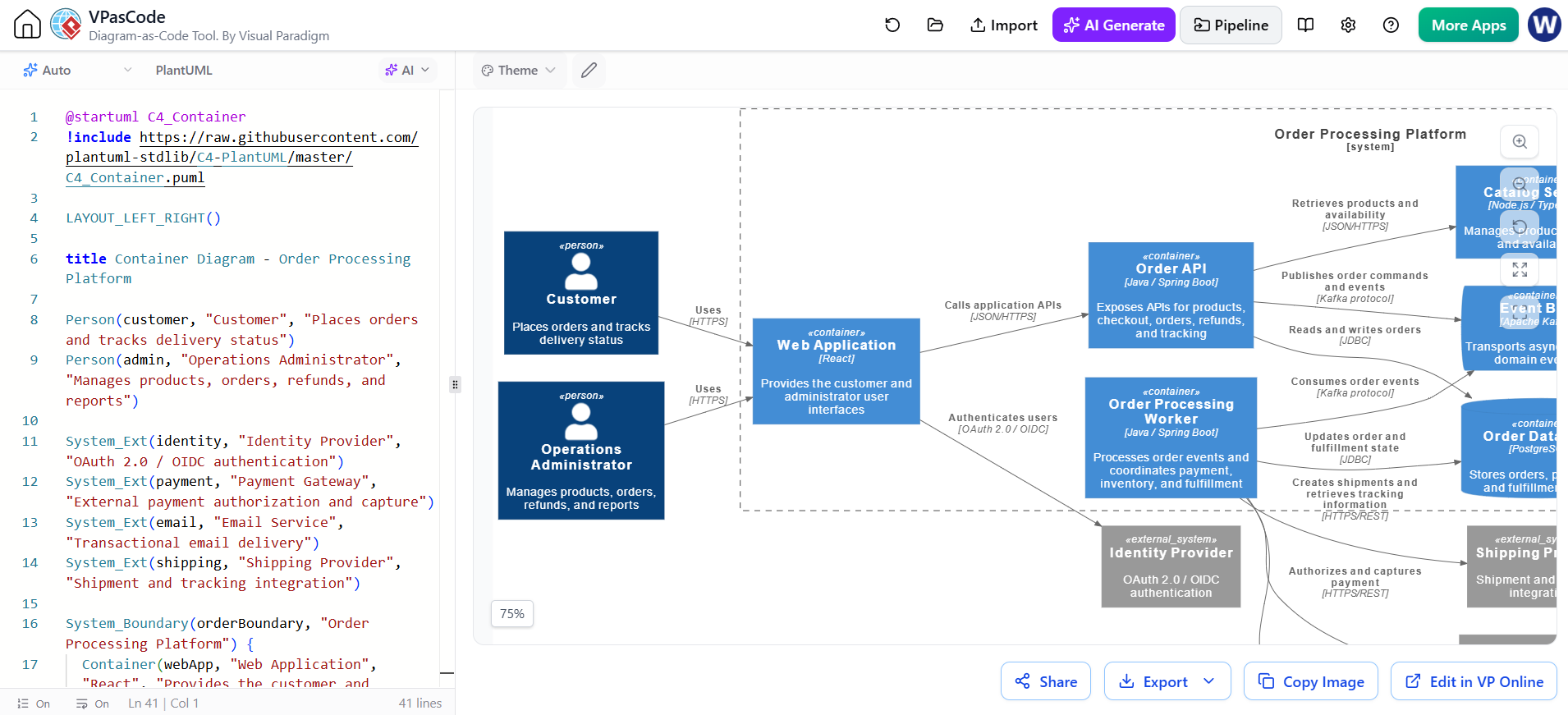
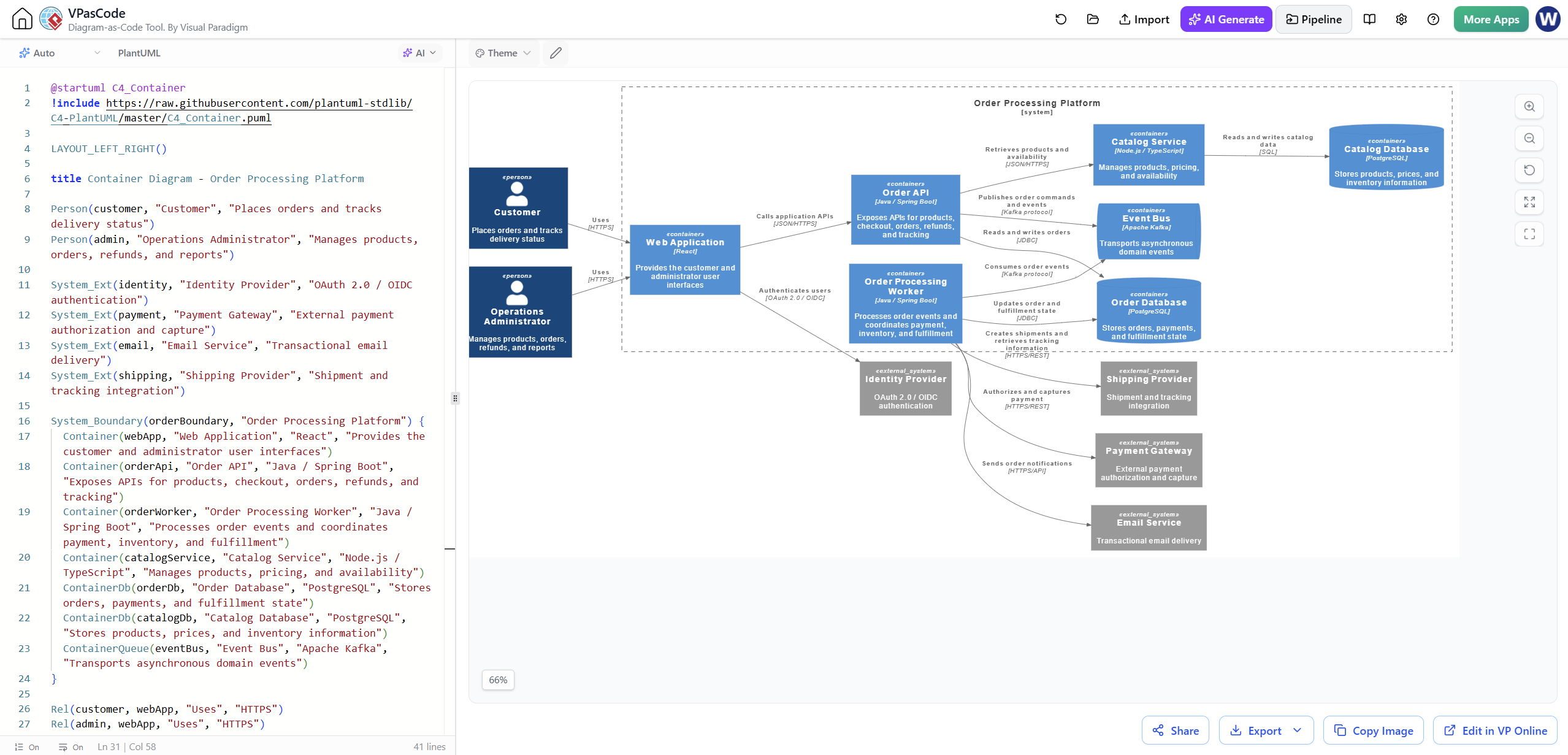
A Container diagram decomposes the system into major applications, services, databases, and message stores.
In C4 terminology, a container does not necessarily mean a Docker container. It means a separately useful or independently deployable part of the system.
C4-PlantUML example
@startuml C4_Container
!include https://raw.githubusercontent.com/plantuml-stdlib/C4-PlantUML/master/C4_Container.puml

LAYOUT_LEFT_RIGHT()

title Container Diagram - Order Processing Platform

Person(customer, "Customer", "Places orders and tracks delivery status")
Person(admin, "Operations Administrator", "Manages products, orders, refunds, and reports")

System_Ext(identity, "Identity Provider", "OAuth 2.0 / OIDC authentication")
System_Ext(payment, "Payment Gateway", "External payment authorization and capture")
System_Ext(email, "Email Service", "Transactional email delivery")
System_Ext(shipping, "Shipping Provider", "Shipment and tracking integration")

System_Boundary(orderBoundary, "Order Processing Platform") {
  Container(webApp, "Web Application", "React", "Provides the customer and administrator user interfaces")
  Container(orderApi, "Order API", "Java / Spring Boot", "Exposes APIs for products, checkout, orders, refunds, and tracking")
  Container(orderWorker, "Order Processing Worker", "Java / Spring Boot", "Processes order events and coordinates payment, inventory, and fulfillment")
  Container(catalogService, "Catalog Service", "Node.js / TypeScript", "Manages products, pricing, and availability")
  ContainerDb(orderDb, "Order Database", "PostgreSQL", "Stores orders, payments, and fulfillment state")
  ContainerDb(catalogDb, "Catalog Database", "PostgreSQL", "Stores products, prices, and inventory information")
  ContainerQueue(eventBus, "Event Bus", "Apache Kafka", "Transports asynchronous domain events")
}

Rel(customer, webApp, "Uses", "HTTPS")
Rel(admin, webApp, "Uses", "HTTPS")
Rel(webApp, identity, "Authenticates users", "OAuth 2.0 / OIDC")
Rel(webApp, orderApi, "Calls application APIs", "JSON/HTTPS")
Rel(orderApi, orderDb, "Reads and writes orders", "JDBC")
Rel(orderApi, catalogService, "Retrieves products and availability", "JSON/HTTPS")
Rel(orderApi, eventBus, "Publishes order commands and events", "Kafka protocol")
Rel(catalogService, catalogDb, "Reads and writes catalog data", "SQL")
Rel(orderWorker, eventBus, "Consumes order events", "Kafka protocol")
Rel(orderWorker, orderDb, "Updates order and fulfillment state", "JDBC")
Rel(orderWorker, payment, "Authorizes and captures payment", "HTTPS/REST")
Rel(orderWorker, email, "Sends order notifications", "HTTPS/API")
Rel(orderWorker, shipping, "Creates shipments and retrieves tracking information", "HTTPS/REST")

@enduml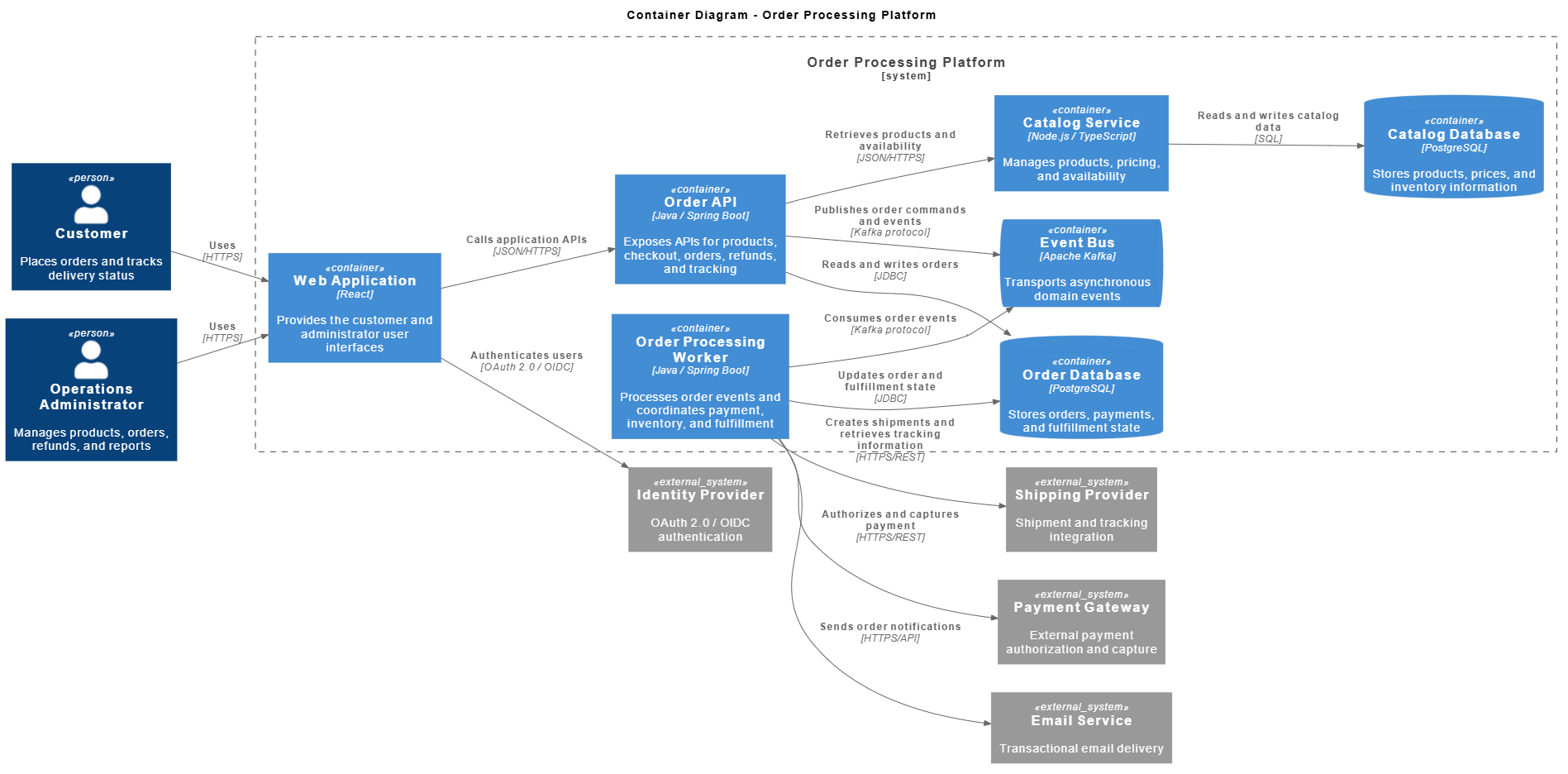
Container review checklist
Check that:
-
Each container has one clear primary responsibility.
-
Databases have explicit owners.
-
Synchronous and asynchronous relationships are distinguishable.
-
APIs are not confused with databases.
-
External systems remain outside the system boundary.
-
Technology choices are specified consistently.
-
The diagram is readable without implementation-level detail.
6. Level 3: Component Diagram
A Component diagram zooms into one container. For example, the Order API may contain controllers, application services, domain services, repositories, and integration adapters.
C4-PlantUML example
@startuml C4_Component
!include https://raw.githubusercontent.com/plantuml-stdlib/C4-PlantUML/master/C4_Component.puml

LAYOUT_LEFT_RIGHT()

title Component Diagram - Order API

Person(customer, "Customer", "Places and tracks orders")

Container(webApp, "Web Application", "React", "Customer and administrator user interface")
ContainerDb(orderDb, "Order Database", "PostgreSQL", "Orders, payments, and fulfillment state")
Container(catalogService, "Catalog Service", "Node.js / TypeScript", "Products, pricing, and availability")
Container(eventBus, "Event Bus", "Apache Kafka", "Asynchronous domain events")

System_Ext(identity, "Identity Provider", "OAuth 2.0 / OIDC")

Container_Boundary(orderApi, "Order API") {
  Component(authController, "Authentication Controller", "REST Controller", "Validates tokens and establishes the authenticated user context")
  Component(productController, "Product Controller", "REST Controller", "Handles product and availability queries")
  Component(orderController, "Order Controller", "REST Controller", "Accepts checkout requests and exposes order status")
  Component(orderApplicationService, "Order Application Service", "Application Service", "Coordinates checkout and order lifecycle use cases")
  Component(orderDomainService, "Order Domain Service", "Domain Service", "Validates order rules and calculates order state transitions")
  Component(paymentPort, "Payment Port", "Output Port", "Abstracts payment authorization from the domain")
  Component(orderRepository, "Order Repository", "Repository", "Persists and retrieves orders")
  Component(eventPublisher, "Domain Event Publisher", "Messaging Adapter", "Publishes OrderPlaced and OrderCancelled events")
}

Rel(customer, webApp, "Uses", "HTTPS")
Rel(webApp, authController, "Sends authenticated requests", "JSON/HTTPS")
Rel(authController, identity, "Validates access tokens", "OAuth 2.0 / OIDC")
Rel(webApp, productController, "Requests product data", "JSON/HTTPS")
Rel(webApp, orderController, "Creates and tracks orders", "JSON/HTTPS")
Rel(productController, catalogService, "Retrieves products and availability", "JSON/HTTPS")
Rel(orderController, orderApplicationService, "Invokes checkout use cases")
Rel(orderApplicationService, orderDomainService, "Executes order business rules")
Rel(orderApplicationService, paymentPort, "Requests payment authorization")
Rel(orderApplicationService, orderRepository, "Loads and saves orders")
Rel(orderApplicationService, eventPublisher, "Publishes domain events")
Rel(orderRepository, orderDb, "Reads and writes order data", "SQL")
Rel(eventPublisher, eventBus, "Publishes order events", "Kafka protocol")

@enduml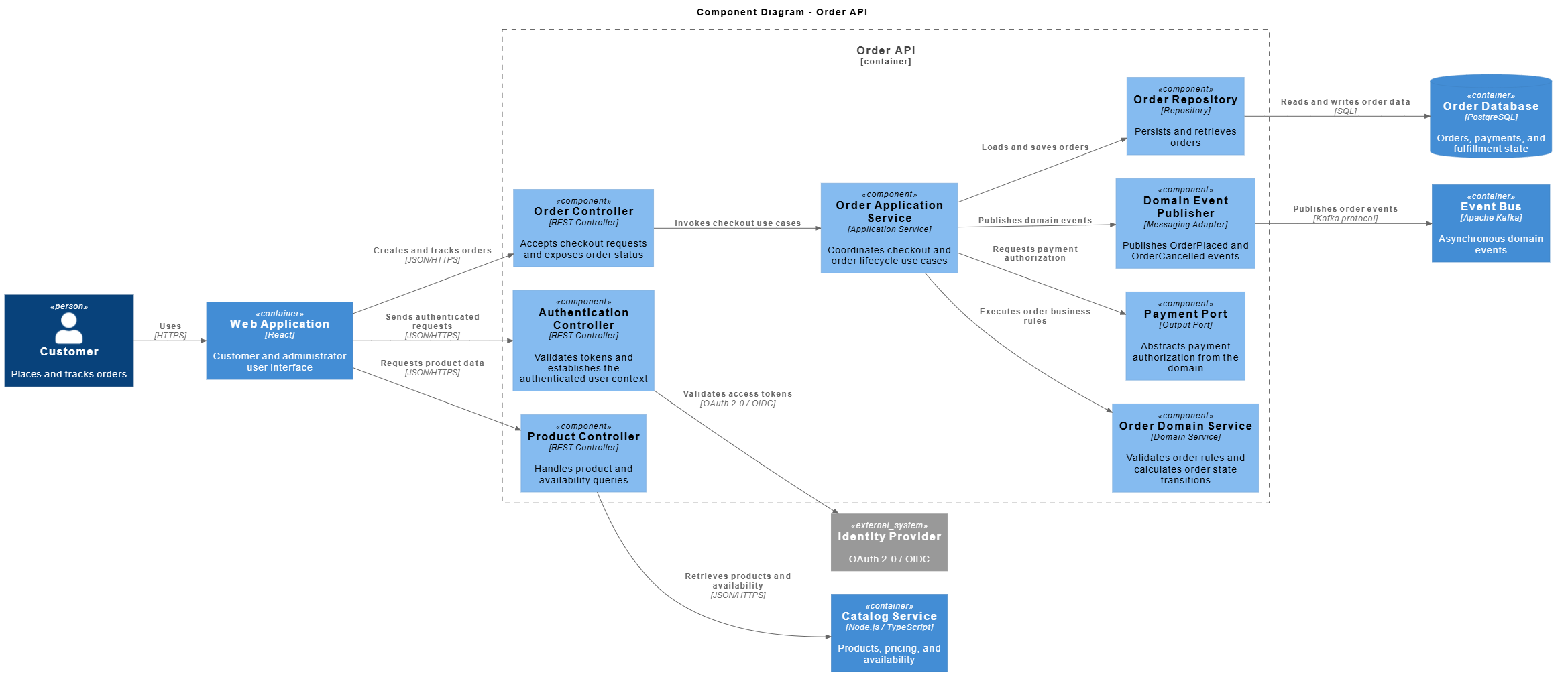
Component modeling guidelines
A component should generally:
-
Have one cohesive responsibility
-
Be understandable without reading its source code
-
Participate in one or more meaningful architectural relationships
-
Be useful when discussing design, testing, ownership, or change impact
Avoid creating components that are merely technical artifacts, such as:
-
StringUtils -
CommonHelper -
BaseController -
ConfigManager
Unless those elements have significant architectural responsibility, they belong in code-level documentation rather than a C4 Component diagram.
7. Dynamic Diagram
A Dynamic diagram explains how containers or components collaborate for a particular scenario.
For example, the checkout process may be:
-
Customer submits checkout.
-
Order API validates the cart.
-
Payment is authorized.
-
The order is stored.
-
An
OrderPlacedevent is published. -
The worker creates a shipment.
-
A confirmation email is sent.
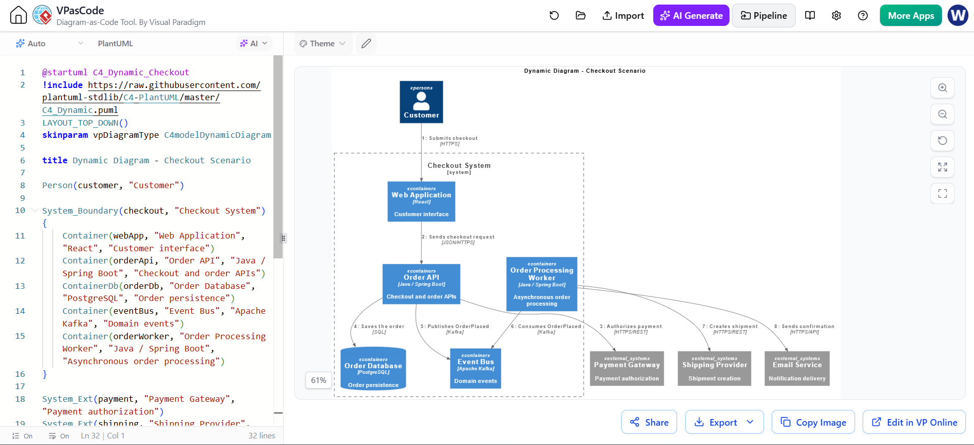
@startuml C4_Dynamic_Checkout
!include https://raw.githubusercontent.com/plantuml-stdlib/C4-PlantUML/master/C4_Dynamic.puml
LAYOUT_TOP_DOWN()
skinparam vpDiagramType C4modelDynamicDiagram

title Dynamic Diagram - Checkout Scenario

Person(customer, "Customer")

System_Boundary(checkout, "Checkout System") {
    Container(webApp, "Web Application", "React", "Customer interface")
    Container(orderApi, "Order API", "Java / Spring Boot", "Checkout and order APIs")
    ContainerDb(orderDb, "Order Database", "PostgreSQL", "Order persistence")
    Container(eventBus, "Event Bus", "Apache Kafka", "Domain events")
    Container(orderWorker, "Order Processing Worker", "Java / Spring Boot", "Asynchronous order processing")
}

System_Ext(payment, "Payment Gateway", "Payment authorization")
System_Ext(shipping, "Shipping Provider", "Shipment creation")
System_Ext(email, "Email Service", "Notification delivery")

Rel(customer, webApp, "Submits checkout", "HTTPS")
Rel(webApp, orderApi, "Sends checkout request", "JSON/HTTPS")
Rel(orderApi, payment, "Authorizes payment", "HTTPS/REST")
Rel(orderApi, orderDb, "Saves the order", "SQL")
Rel(orderApi, eventBus, "Publishes OrderPlaced", "Kafka")
Rel(orderWorker, eventBus, "Consumes OrderPlaced", "Kafka")
Rel(orderWorker, shipping, "Creates shipment", "HTTPS/REST")
Rel(orderWorker, email, "Sends confirmation", "HTTPS/API")

@enduml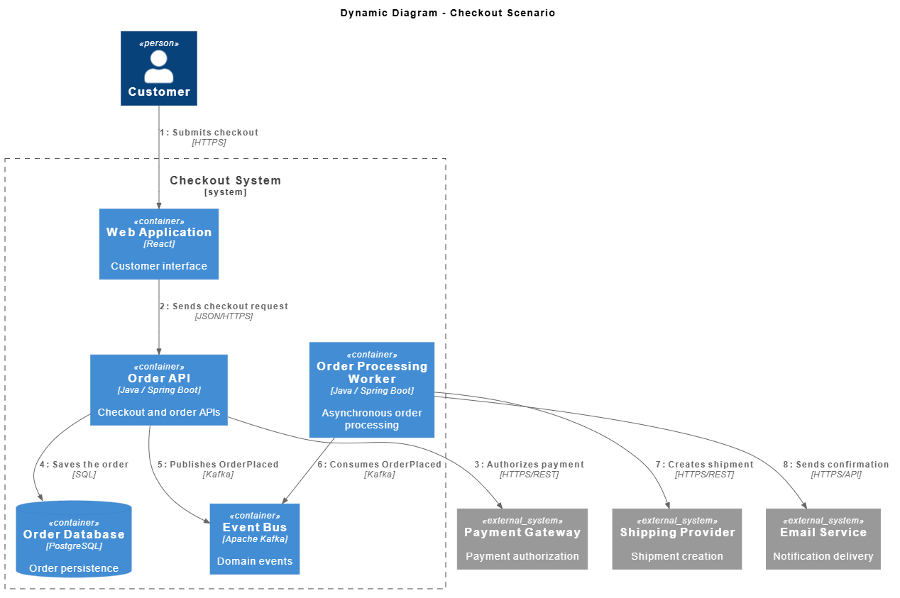
Dynamic diagrams should be created for important use cases, not every possible request. Useful scenarios include:
-
User login
-
Checkout
-
Refund processing
-
Password reset
-
Order cancellation
-
Inventory reservation
-
Service failure and retry
-
Disaster recovery
8. Deployment Diagram
A Deployment diagram shows the mapping between software containers and infrastructure nodes.
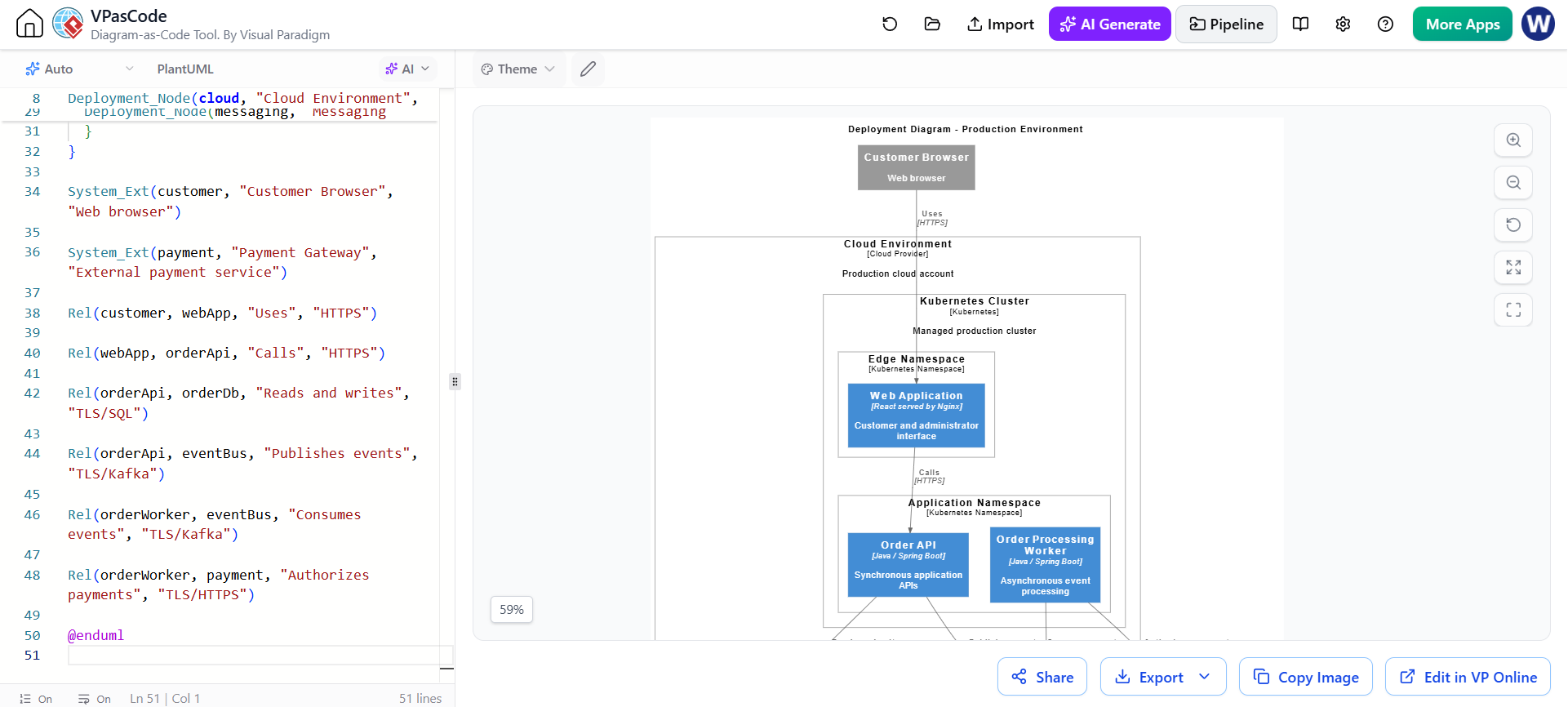
@startuml C4_Deployment
!include https://raw.githubusercontent.com/plantuml-stdlib/C4-PlantUML/master/C4_Deployment.puml
LAYOUT_WITH_LEGEND()
skinparam vpDiagramType C4modelDeploymentDiagram

title Deployment Diagram - Production Environment

Deployment_Node(cloud, "Cloud Environment", "Cloud Provider", "Production cloud account") {

  Deployment_Node(kubernetes, "Kubernetes Cluster", "Kubernetes", "Managed production cluster") {

    Deployment_Node(edge, "Edge Namespace", "Kubernetes Namespace") {
      Container(webApp, "Web Application", "React served by Nginx", "Customer and administrator interface")
    }

    Deployment_Node(application, "Application Namespace", "Kubernetes Namespace") {
      Container(orderApi, "Order API", "Java / Spring Boot", "Synchronous application APIs")

      Container(orderWorker, "Order Processing Worker", "Java / Spring Boot", "Asynchronous event processing")
    }
  }

  Deployment_Node(data, "Managed Data Services", "Cloud Services") {
    ContainerDb(orderDb, "Order Database", "Managed PostgreSQL", "Orders and payment state")

    ContainerDb(catalogDb, "Catalog Database", "Managed PostgreSQL", "Products and inventory")
  }

  Deployment_Node(messaging, "Messaging Services", "Managed Kafka") {
    ContainerQueue(eventBus, "Event Bus", "Managed Kafka", "Order and fulfillment events")
  }
}

System_Ext(customer, "Customer Browser", "Web browser")

System_Ext(payment, "Payment Gateway", "External payment service")

Rel(customer, webApp, "Uses", "HTTPS")

Rel(webApp, orderApi, "Calls", "HTTPS")

Rel(orderApi, orderDb, "Reads and writes", "TLS/SQL")

Rel(orderApi, eventBus, "Publishes events", "TLS/Kafka")

Rel(orderWorker, eventBus, "Consumes events", "TLS/Kafka")

Rel(orderWorker, payment, "Authorizes payments", "TLS/HTTPS")

@enduml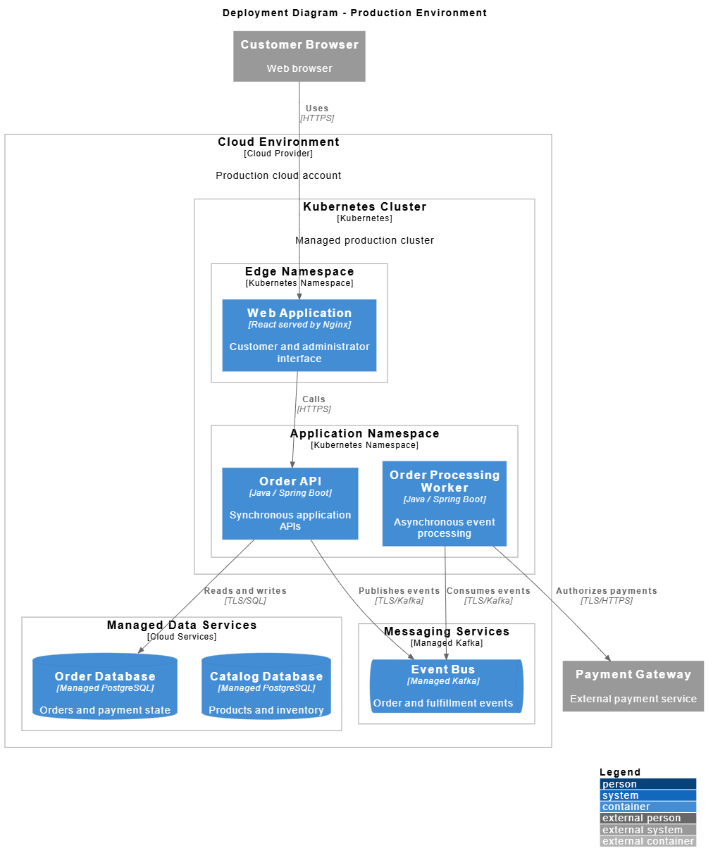
Deployment diagrams should document:
-
Runtime nodes
-
Regions and availability zones
-
Network boundaries
-
Service placement
-
Database placement
-
External integrations
-
Replication and failover where relevant
-
Security zones
-
Protocols and encryption
9. Using the Visual Paradigm AI Chatbot
The AI Chatbot is most useful for rapidly creating an initial architecture model from structured requirements. It should be treated as a drafting assistant, not as the final authority on system design.
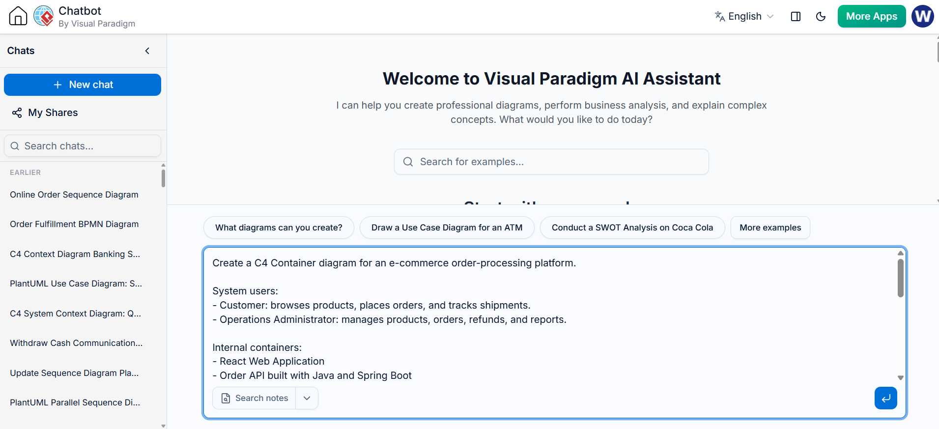
Example prompt
Create a C4 Container diagram for an e-commerce order-processing platform.

System users:
- Customer: browses products, places orders, and tracks shipments.
- Operations Administrator: manages products, orders, refunds, and reports.

Internal containers:
- React Web Application
- Order API built with Java and Spring Boot
- Order Processing Worker
- Catalog Service built with Node.js and TypeScript
- PostgreSQL Order Database
- PostgreSQL Catalog Database
- Kafka Event Bus

External systems:
- OAuth 2.0 Identity Provider
- Payment Gateway
- Email Service
- Shipping Provider

Show:
- System boundaries
- Synchronous versus asynchronous communication
- Protocols
- Responsibilities for each container
- Clear relationship labels
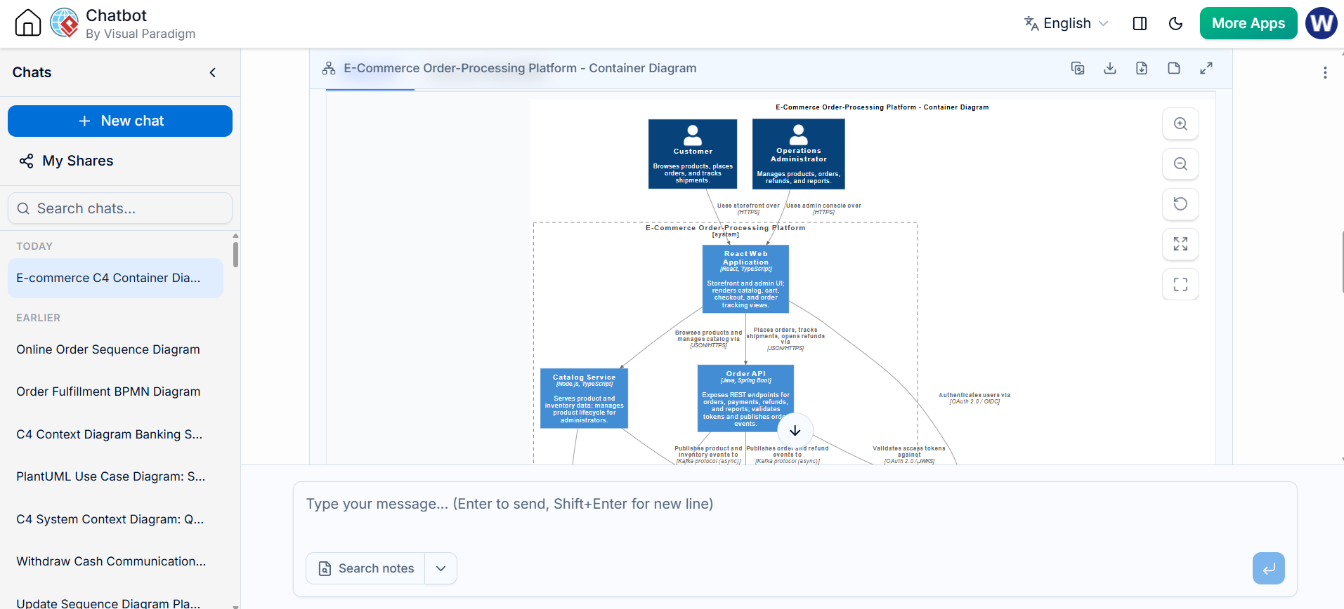
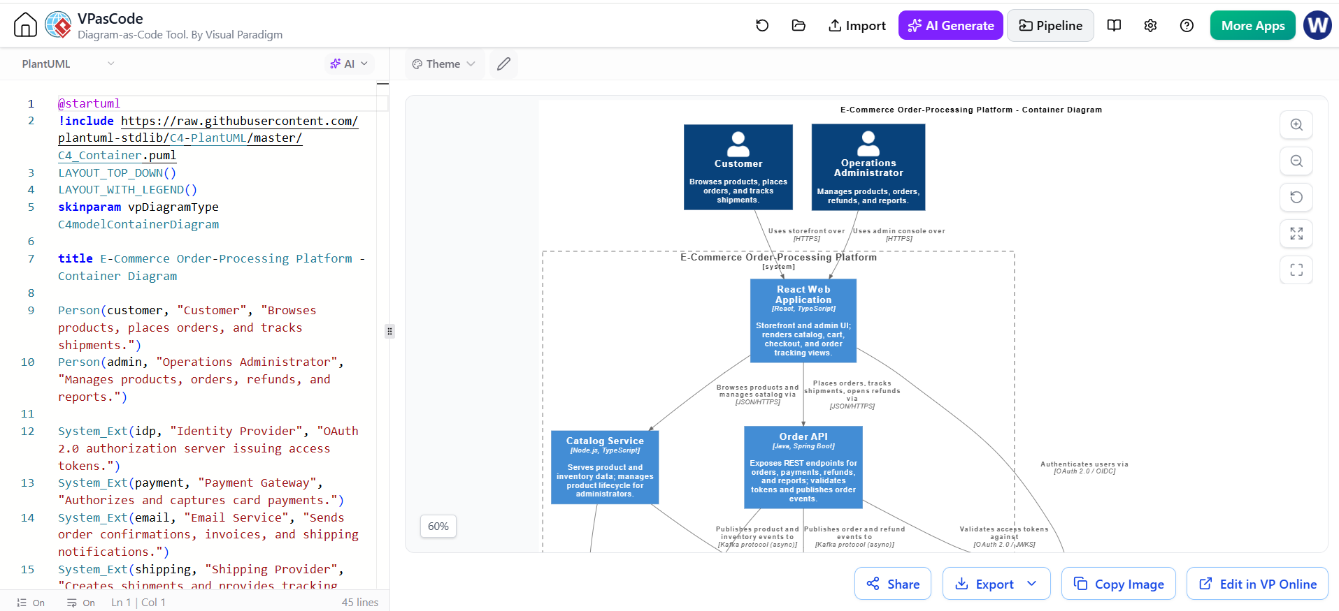
Send to Pipeline for Refinement and view the PlantUML Source
Better prompts include
-
Business actors
-
System boundaries
-
Responsibilities
-
Technology choices
-
Databases
-
External integrations
-
Protocols
-
Important scenarios
-
Expected diagram level
-
Naming conventions
-
Security constraints
Example refinement prompt
Refine the diagram using these rules:

1. Keep the system boundary around internally owned containers.
2. Place external providers outside the boundary.
3. Label every relationship with purpose and protocol.
4. Distinguish synchronous HTTPS calls from asynchronous Kafka events.
5. Do not add implementation classes.
6. Use concise descriptions of no more than 15 words.
7. Keep the diagram readable from left to right.
8. Add a legend explaining the technologies.
The AI C4 workflow can generate a first diagram, allow visual inspection, and then pass the result to VPasCode for code-level refinement. <citation src="3"></citation>
10. Using VPasCode
VPasCode is appropriate when the team wants diagrams to behave like source code:
-
Editable as text
-
Reviewable in pull requests
-
Reproducible
-
Easy to duplicate
-
Suitable for CI/CD rendering
-
Convenient for developers and architects
VPasCode supports PlantUML C4 models and provides live code-to-diagram rendering. It can also generate diagrams from natural-language prompts and fix syntax issues with AI assistance.
Typical workflow
-
Open VPasCode.
-
Create a PlantUML document.
-
Paste a C4-PlantUML script.
-
Preview the rendered diagram.
-
Correct syntax and layout.
-
Export the result as an image or document.
-
Save the PlantUML source in Git.
-
Review changes through pull requests.
Suggested repository structure
architecture/
├── README.md
├── c4/
│   ├── 01-system-context.puml
│   ├── 02-container.puml
│   ├── 03-order-api-component.puml
│   ├── 04-checkout-dynamic.puml
│   └── 05-production-deployment.puml
├── adr/
│   ├── ADR-001-event-driven-order-processing.md
│   └── ADR-002-payment-provider-selection.md
└── docs/
    └── architecture-overview.md
Version-control recommendations
Commit:
-
.pumlsource files -
Architecture decision records
-
Diagram descriptions
-
Rendering instructions
-
Optional generated SVG or PNG files
Avoid treating exported images as the only source of truth. The PlantUML code should remain authoritative.
Example Git workflow
git checkout -b architecture/update-order-processing
vim architecture/c4/02-container.puml
git diff
git add architecture/c4/02-container.puml
git commit -m "Document asynchronous order processing"
git push origin architecture/update-order-processing
11. Moving Between VPasCode and Visual Paradigm
Use VPasCode for rapid source-oriented iteration and Visual Paradigm for formal visual modeling and stakeholder communication.
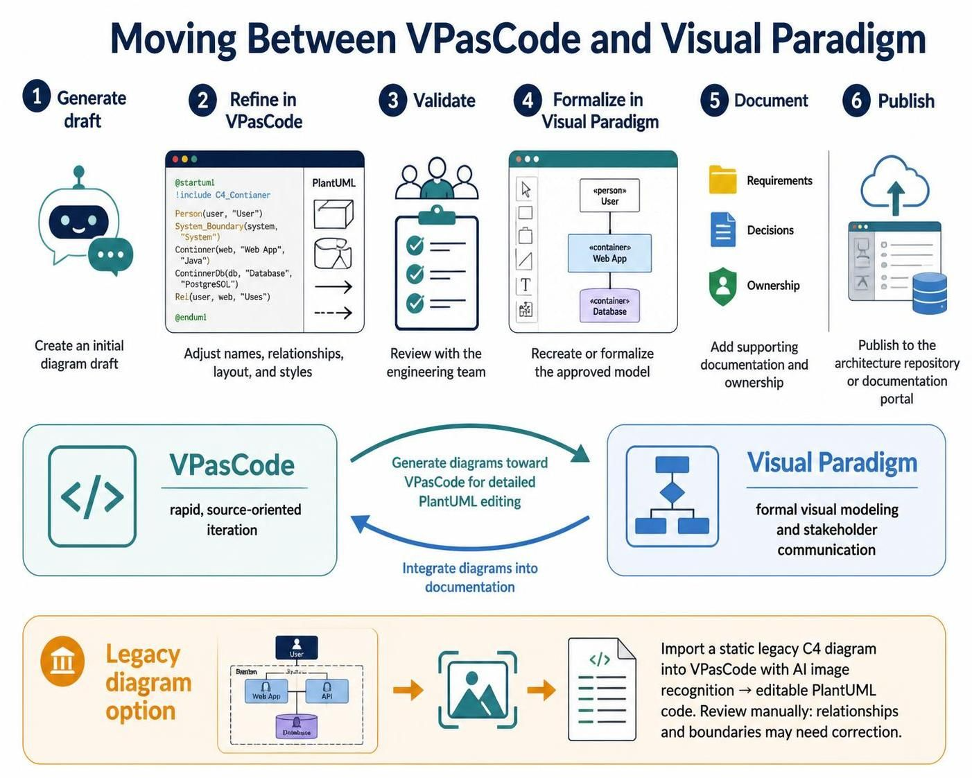
A useful workflow is:
-
Generate a draft with the AI Chatbot.
-
Open or copy the diagram code into VPasCode.
-
Refine names, relationships, layout, and styles.
-
Validate the model with the engineering team.
-
Recreate or formalize the approved model in Visual Paradigm.
-
Add supporting documentation, requirements, decisions, and ownership information.
-
Publish the approved diagram in the architecture repository or documentation portal.
Visual Paradigm’s current workflow also supports sending generated diagrams toward VPasCode for detailed PlantUML editing and integrating diagrams into documentation.
If you have only a static legacy diagram, VPasCode also provides an AI-based C4 image-import workflow that converts an image into editable PlantUML code. The generated code should still be reviewed manually because image recognition cannot reliably infer every architectural relationship or boundary.
12. Diagram Governance
A C4 model becomes valuable when it stays current.
Ownership
Assign an owner to each diagram:
| Diagram | Suggested owner |
|---|---|
| System Context | Enterprise or solution architect |
| Container | Solution architect and lead engineers |
| Component | Service or team owner |
| Dynamic | Feature team or domain owner |
| Deployment | Platform or DevOps team |
Update triggers
Update diagrams when:
-
A new container is introduced
-
A service is retired
-
A database ownership boundary changes
-
An external integration changes
-
A deployment topology changes
-
A major security boundary changes
-
A significant architectural decision is approved
Review cadence
A practical schedule is:
-
Review System Context: quarterly
-
Review Container: every major release
-
Review Component: when internal design changes
-
Review Deployment: whenever infrastructure changes
-
Review Dynamic diagrams: when critical workflows change
Metadata to include
Each diagram should have:
-
Title
-
Scope
-
Owner
-
Last reviewed date
-
Version or release
-
Environment, if applicable
-
Links to ADRs
-
Links to service repositories
-
Legend for technologies and protocols
Example footer:
Owner: Order Platform Team
Last reviewed: 2026-09-27
Scope: Production order-processing architecture
Source: architecture/c4/02-container.puml
13. Common Mistakes
Mixing abstraction levels
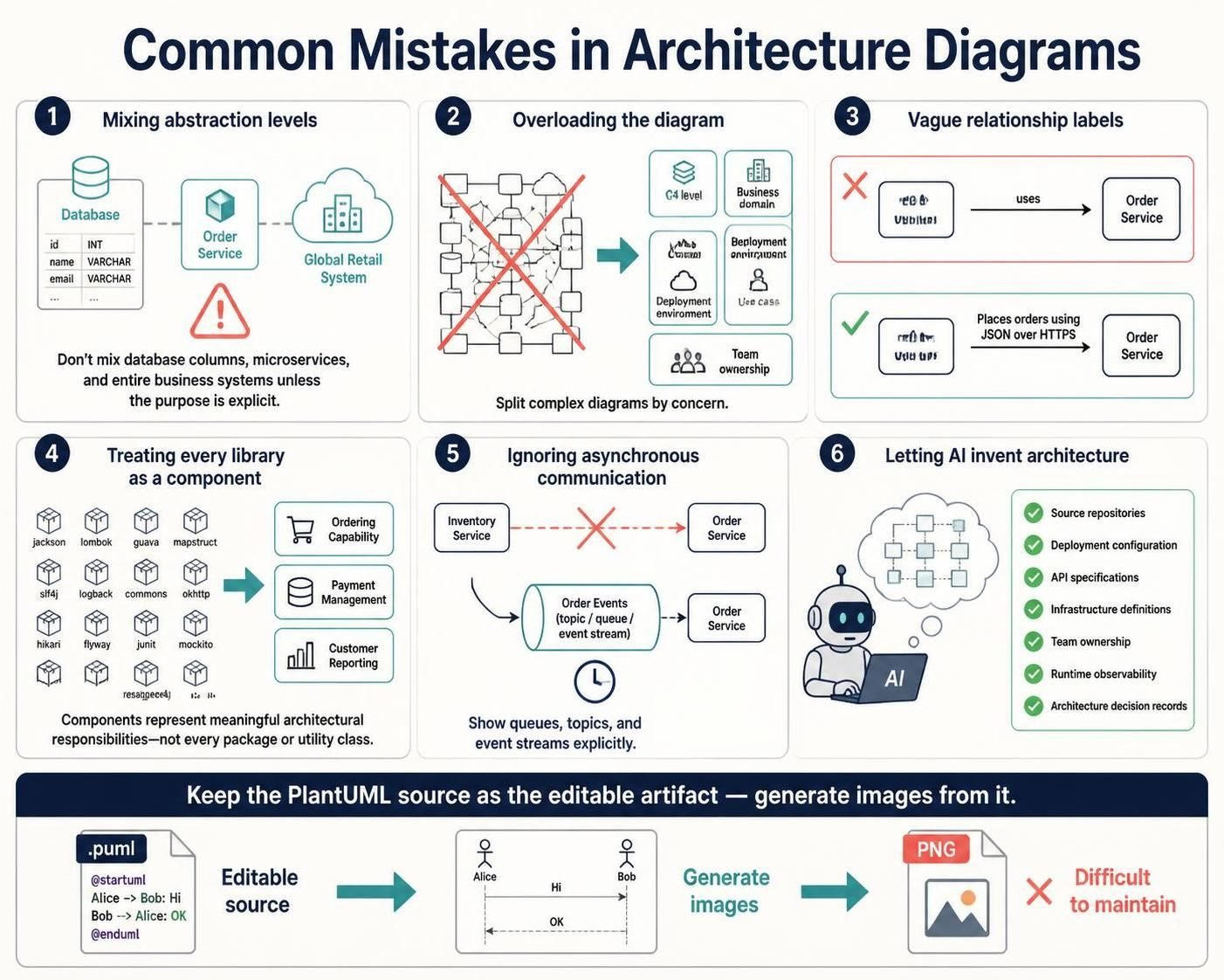
Do not place a database column, a microservice, and an entire business system on the same diagram unless the purpose is explicitly explained.
Overloading the diagram
If a diagram is difficult to read, split it by:
-
C4 level
-
Business domain
-
Deployment environment
-
Use case
-
Team ownership
Vague relationship labels
Replace:
uses
with:
Places orders using JSON over HTTPS
Treating every library as a component
C4 components should represent meaningful architectural responsibilities, not every package or utility class.
Ignoring asynchronous communication
Queues, topics, and event streams should be shown explicitly. Otherwise, readers may assume every interaction is synchronous.
Letting AI invent architecture
AI can infer plausible services, protocols, and relationships that do not exist. Validate all generated diagrams against:
-
Source repositories
-
Deployment configuration
-
API specifications
-
Infrastructure definitions
-
Team ownership
-
Runtime observability
-
Architecture decision records
Keeping only exported images
A PNG is difficult to maintain. Keep the PlantUML source as the editable artifact and generate images from it.
14. Recommended End-to-End Process
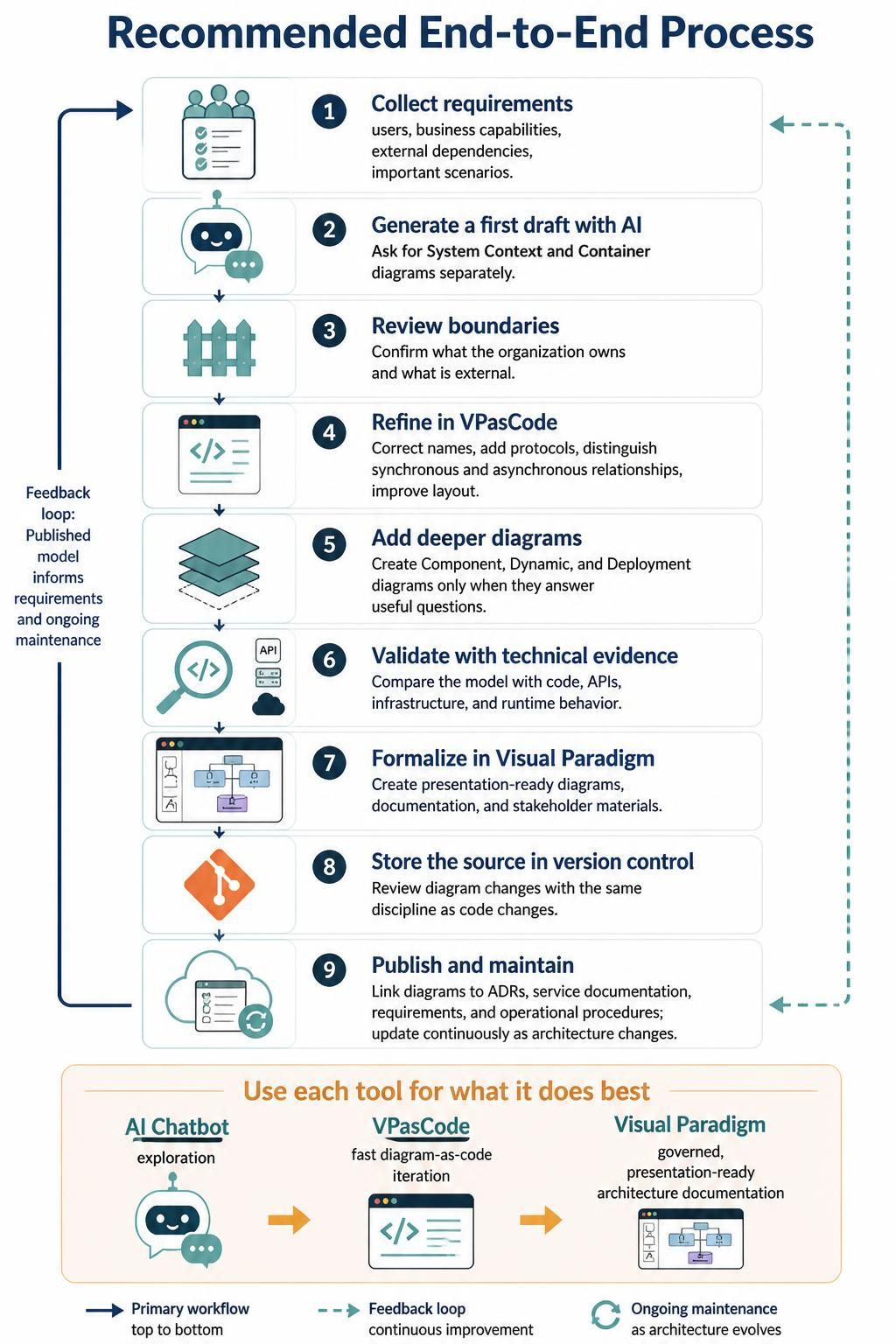
-
Collect requirements
Identify users, business capabilities, external dependencies, and important scenarios. -
Generate a first draft with AI
Ask for a System Context and Container diagram separately. -
Review boundaries
Confirm what the organization owns and what is external. -
Refine in VPasCode
Correct names, add protocols, distinguish synchronous and asynchronous relationships, and improve layout. -
Add deeper diagrams
Create Component, Dynamic, and Deployment diagrams only where they answer useful questions. -
Validate with technical evidence
Compare the model with code, APIs, infrastructure, and runtime behavior. -
Formalize in Visual Paradigm
Use the C4 modeling tool for polished diagrams, documentation, and stakeholder presentation. -
Store the source in version control
Review diagram changes with the same discipline as code changes. -
Publish the model
Link diagrams to ADRs, service documentation, requirements, and operational procedures. -
Maintain continuously
Update diagrams when architecture changes, rather than during a once-a-year documentation exercise.
The most effective approach is therefore not to choose between Visual Paradigm, AI, and VPasCode. Use the AI Chatbot for exploration, VPasCode for fast diagram-as-code iteration, and Visual Paradigm for governed, presentation-ready architecture documentation.
Visual Paradigm Tooling: Recommended Articles & Posts
Visual Paradigm C4 Model
- From Big Picture to Code: A Beginner’s Guide to Visualizing Software Architecture with the C4 Model: Comprehensive beginner’s guide covering C4 levels with a PayQuick payment platform example and PlantUML code snippets for context, container, and component diagrams .
- How to Build Microservice Architecture Models with PlantUML and C4: Step-by-step guide for designing microservice architectures using PlantUML and C4, including system context and container diagram examples with AI error-fixing tips .
- Comprehensive Guide to Using the New C4 Model Support in Visual Paradigm Desktop: Detailed walkthrough of Visual Paradigm Desktop’s native C4 support (six diagram types), including when to use each level and step-by-step creation instructions .
- AI C4 Model Architecture Generator | Visual Paradigm AI Diagramming Chatbot: Overview of AI-powered C4 generation capabilities, showing how to describe architecture in plain English and get System Context, Container, Component, and Deployment diagrams .
Visual Paradigm Chatbot
- How to Create UML Sequence Diagram with AI Chatbot: Hands-on tutorial demonstrating how to generate a UML Sequence Diagram for an online shopping checkout process using the AI Chatbot with natural language prompts .
- AI Chatbot: A Comprehensive Guide to Visual Modeling: In-depth guide covering the AI Chatbot’s capabilities including instant diagram generation, conversational refinement, intelligent model analysis, and real-world examples across UML, ArchiMate, C4, and BPMN .
- AI VPP Chatbot | Visual Paradigm: Overview of the specialized project chatbot that analyzes uploaded .vpp files, enabling natural language queries about diagrams, use cases, and flow of events with enterprise endpoint management options .
- From “Drawing Chores” to “Articulation” — Visual Paradigm AI Ecosystem: Explains how the AI Chatbot fits into Visual Paradigm’s broader AI ecosystem, covering conversational refinement, educational mode, and export to desktop projects .
VPasCode (Diagram-as-Code)
- VPasCode: AI-Assisted Diagram-as-Code with PlantUML: Comprehensive guide covering prompting strategies for better diagrams, syntax and semantic review checklists, version-controlling VPasCode diagrams, and PlantUML layout techniques .
- 60-Second Quickstart Guide | VPasCode Text to Diagram Guide: Fast walkthrough of VPasCode’s dual-panel editor, demonstrating Mermaid flowchart and PlantUML component examples with export options (SVG, PNG, shareable URL) .
- Native AI Diagram Generation in Visual Paradigm VPasCode: Announcement and guide for VPasCode’s embedded AI capabilities, including instant generation from natural language prompts, AI-based modifications with code diff preview, and automatic syntax error fixing .
- VPasCode: AI-Assisted Diagram-as-Code with PlantUML, Mermaid, and Graphviz: Extensive reference covering Mermaid, PlantUML, and Graphviz syntax examples in VPasCode, with best practices for each language including C4 system-context diagrams and component diagrams .
- 在 VPasCode 中绘制您的第一个图表——5 分钟快速入门: Five-minute Chinese-language quickstart covering AI prompt-based generation (“为 ATM 系统生成一个 PlantUML 用例图”), manual Mermaid coding, live preview, and export/share features .
Related posts:
 The Comprehensive Guide to the C4 Model for Software Architecture
 A Practical Guide to C4 Modeling with AI-Powered Visual Paradigm Tools: Architecting Scalable E-Commerce Systems
 A Comprehensive Case Study on Building C4 Diagrams with Visual Paradigm’s Multi-Method Approach
 From Concept to Code: Mastering CRC Card Diagrams with Visual Paradigm’s AI

 English
 Arabic
 Chinese (Simplified)
 Dutch
Dutch French
 German
 Italian
 Japanese
 Korean
 Portuguese
 Russian
 Spanish