


Introduction
UML offers a broad vocabulary for describing software systems, but effective modeling does not require using every available diagram type. In practice, a carefully selected subset is sufficient to communicate most of the information needed during requirements analysis, process design, software architecture, implementation, testing, and deployment.
This guide presents a practical “minimum effective UML” approach centered on seven diagram types: use case, activity, sequence, class, component, deployment, and state-machine diagrams. Each type answers a different question, from who uses the system and how work flows to how components collaborate, where the system runs, and how important entities change over time.
The guide also explains how to combine Visual Paradigm UML, VPasCode, PlantUML, and AI-assisted modeling. Visual Paradigm is useful for graphical modeling, traceability, documentation, and repository-based collaboration. VPasCode and PlantUML support text-based, version-controlled diagrams that can be reviewed and maintained alongside source code. AI can accelerate diagram creation and review, provided that its output is validated against real requirements, implementation details, and operational constraints.
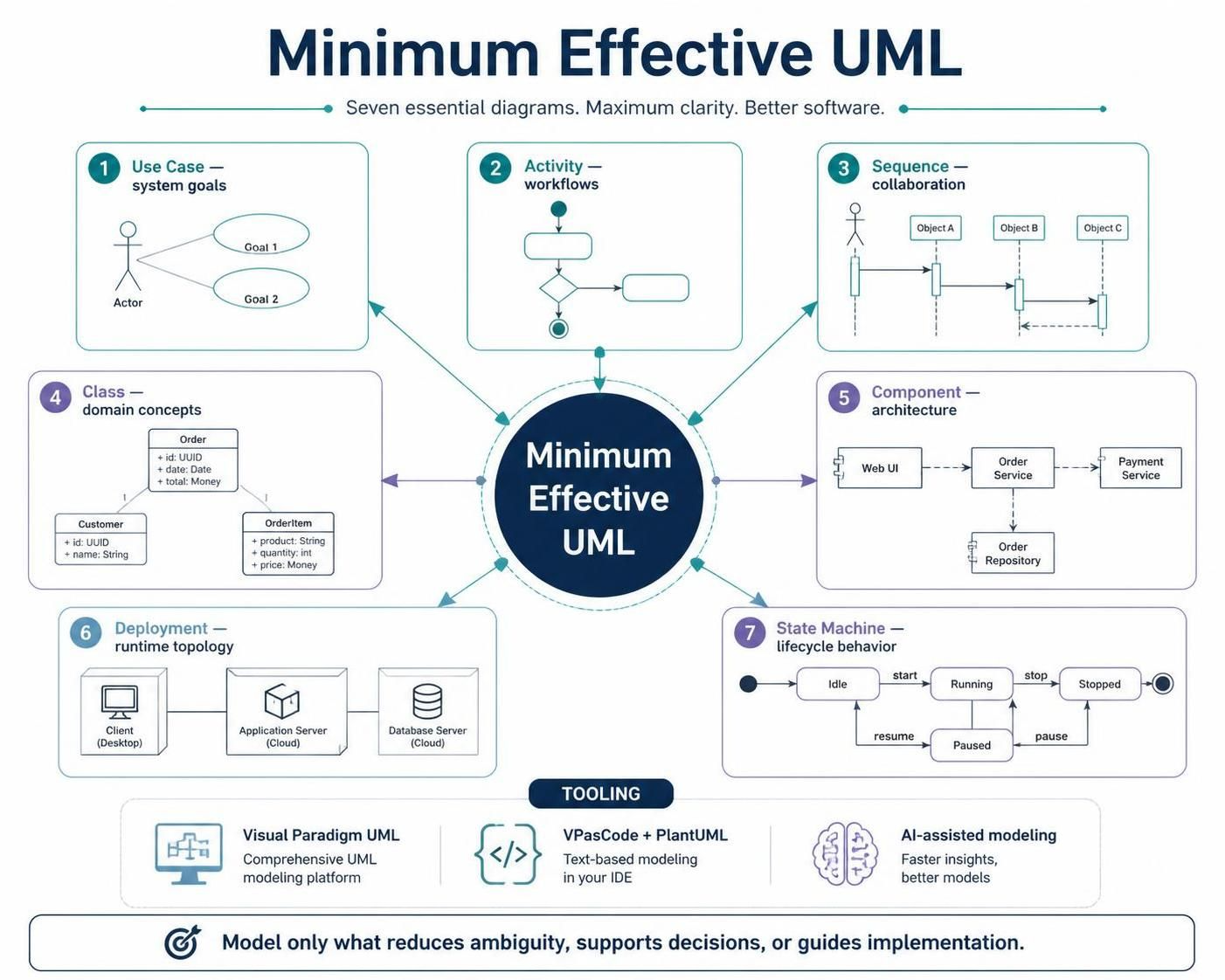
The objective is not to produce more diagrams. It is to create the smallest set of clear, maintainable models that helps a team make better engineering decisions.
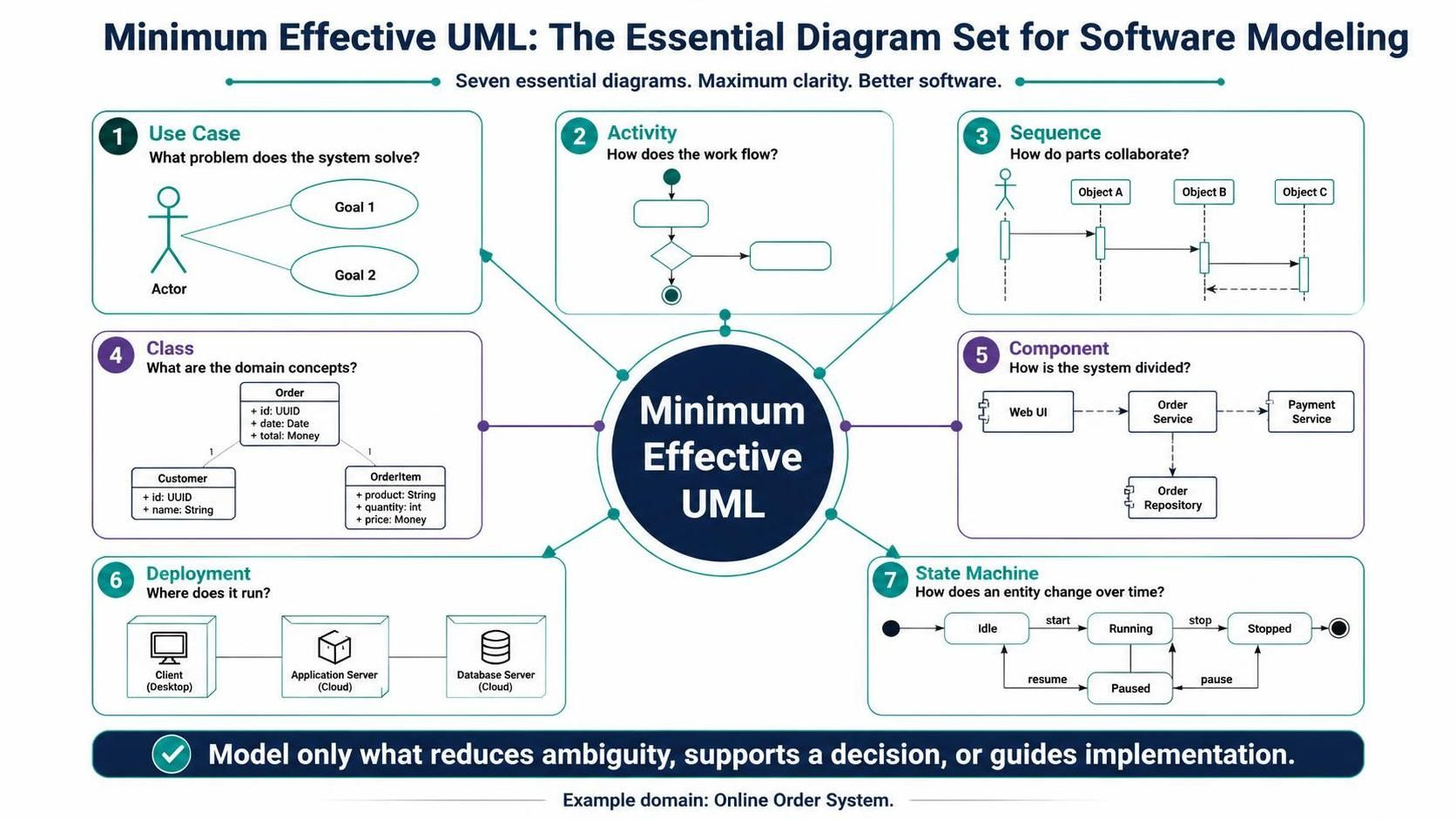
Minimum Effective UML: The Essential Diagram Set for Software Modeling
You do not need all UML diagram types to model a software system effectively. A small, deliberately chosen set covers the questions that matter most:
-
What problem does the system solve? — Use case diagram
-
How does the work flow? — Activity diagram
-
How do parts collaborate in a scenario? — Sequence diagram
-
What are the important domain concepts? — Class diagram
-
How is the system divided into deployable or replaceable parts? — Component diagram
-
Where does it run? — Deployment diagram
-
How does an important entity change over time? — State-machine diagram, when needed
This is a “minimum effective UML” approach: model only what reduces ambiguity, supports a decision, or guides implementation. UML itself contains a much larger catalog of structure and behavior diagrams, but the subset above covers requirements, workflows, design, architecture, runtime topology, and lifecycle behavior.
The examples below use a fictional online order system.
1. The recommended subset
| Diagram | Primary question | Best audience | Create it |
|---|---|---|---|
| Use case | Who needs what from the system? | Customers, product owners, analysts | At project or feature discovery |
| Activity | What steps, decisions, and responsibilities make up a process? | Business and delivery teams | During requirements and process design |
| Sequence | What messages occur, and in what order? | Developers, testers, integrators | Before implementing important scenarios |
| Class | What concepts, data, and relationships must the design represent? | Developers, architects | During domain and detailed design |
| Component | What are the system’s major modules and interfaces? | Architects, developers, operations | During architecture and integration design |
| Deployment | On which nodes, containers, or services does the system run? | Developers, DevOps, security, operations | Before release and when infrastructure changes |
| State machine | What valid states and transitions govern an entity? | Developers, testers, domain experts | Only for stateful or event-driven behavior |
The first five are usually enough for ordinary CRUD, web, API, and business applications. Add deployment for systems with meaningful infrastructure concerns. Add state-machine diagrams for entities such as orders, payments, tickets, documents, devices, or subscriptions.
2. A diagram selection rule
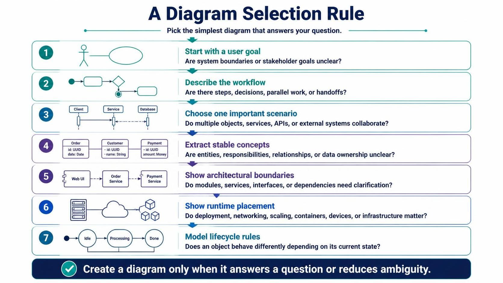
Use the following rule instead of creating diagrams by habit:
-
Start with a user goal.
If the system boundary or stakeholder goals are unclear, create a use case diagram. -
Describe the business or user workflow.
If there are steps, decisions, parallel work, or handoffs, create an activity diagram. -
Choose one important scenario.
If the implementation requires multiple objects, services, APIs, or external systems to collaborate, create a sequence diagram. -
Extract stable concepts.
If the team is debating entities, responsibilities, relationships, or ownership of data, create a class diagram. -
Show architectural boundaries.
If the team needs to understand modules, services, interfaces, or dependencies, create a component diagram. -
Show runtime placement.
If deployment, networking, scaling, containers, devices, or external infrastructure matter, create a deployment diagram. -
Model lifecycle rules.
If an object behaves differently depending on its current state, create a state-machine diagram.
A diagram should have a specific question in its title, such as:
-
“Who can approve an order?”
-
“How does checkout handle payment failure?”
-
“Which component owns inventory reservation?”
-
“Where is the payment service deployed?”
-
“Which transitions are valid for an order?”
3. The end-to-end modeling workflow
Step 1: Capture scope with use cases
Begin with actors and observable system goals. Keep use cases at a useful level of abstraction:
-
“Place order” is useful.
-
“Click the blue button” is usually too detailed.
-
“Run SQL query” is usually an implementation detail.
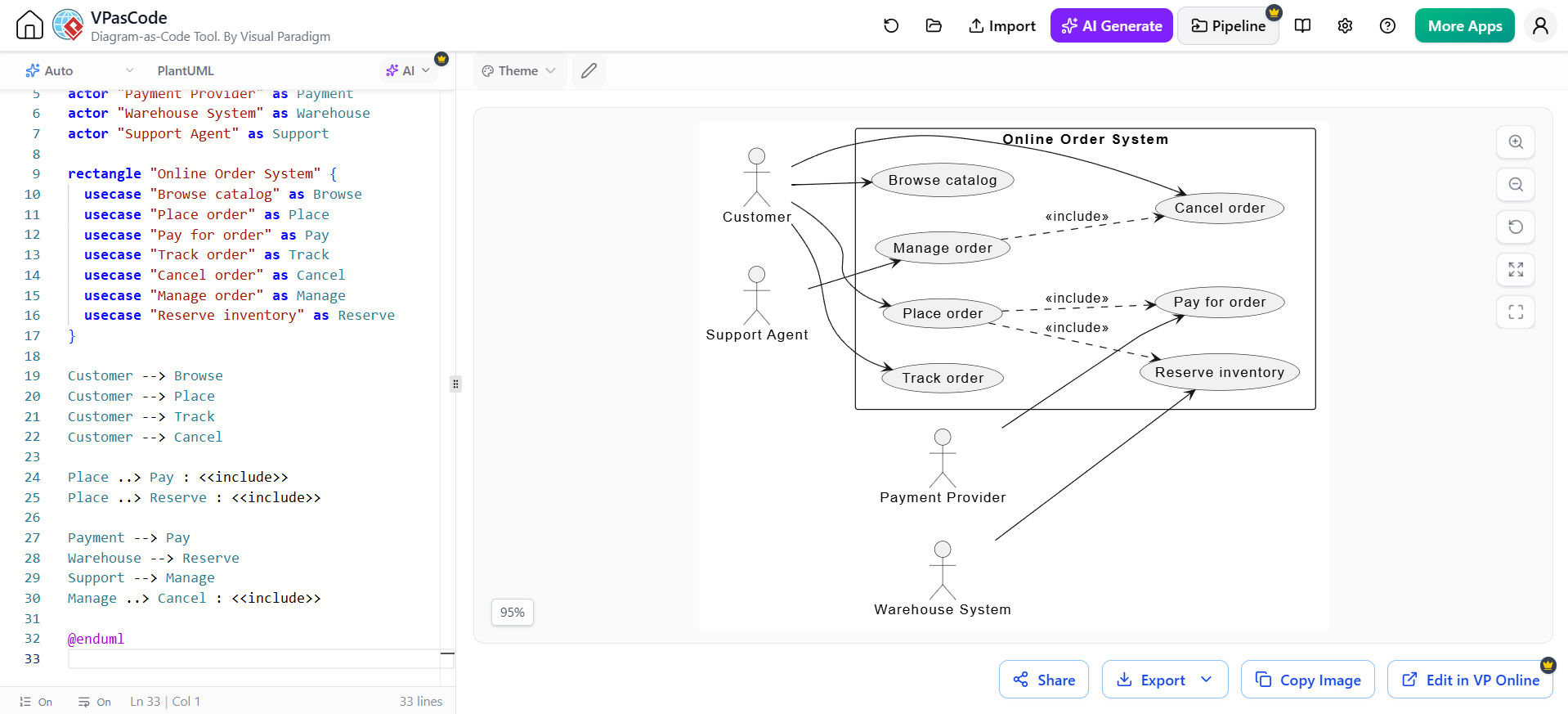
@startuml
left to right direction

actor Customer
actor "Payment Provider" as Payment
actor "Warehouse System" as Warehouse
actor "Support Agent" as Support

rectangle "Online Order System" {
  usecase "Browse catalog" as Browse
  usecase "Place order" as Place
  usecase "Pay for order" as Pay
  usecase "Track order" as Track
  usecase "Cancel order" as Cancel
  usecase "Manage order" as Manage
  usecase "Reserve inventory" as Reserve
}

Customer --> Browse
Customer --> Place
Customer --> Track
Customer --> Cancel

Place ..> Pay : <<include>>
Place ..> Reserve : <<include>>

Payment --> Pay
Warehouse --> Reserve
Support --> Manage
Manage ..> Cancel : <<include>>

@enduml
Use case diagrams are most valuable as a scope map, not as a complete specification. Each important use case should normally have a short textual specification containing:
-
Goal
-
Primary actor
-
Preconditions
-
Trigger
-
Main success scenario
-
Alternative and exception flows
-
Postconditions
-
Business rules
-
Related requirements and tests
Do not overuse <<include>> and <<extend>>. Use include when behavior is mandatory and reused. Use extend when optional or conditional behavior extends a base use case. If the relationship is difficult to explain, a plain association or a written scenario is often clearer.
Step 2: Model the workflow with an activity diagram
Use activity diagrams for business processes, use-case flows, approvals, batch jobs, and algorithms. They are particularly useful when responsibility changes between people, systems, or teams. Activity diagrams support decisions, iteration, concurrency, and swimlanes.
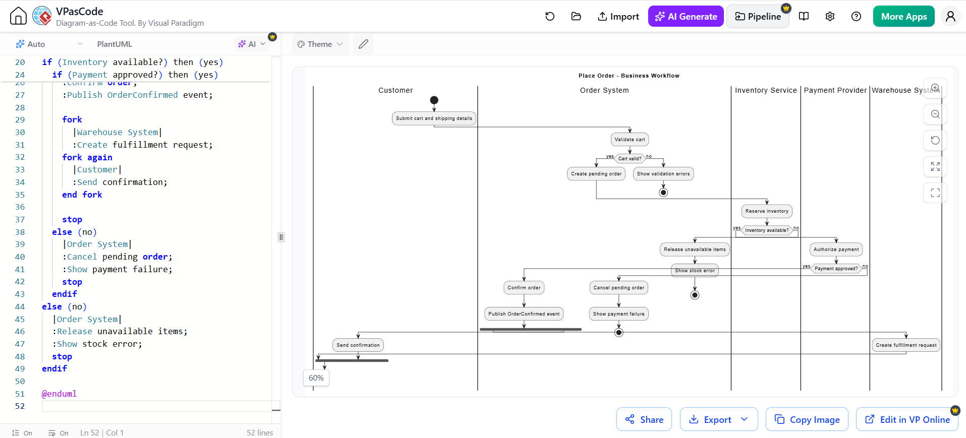
@startuml
title Place Order - Business Workflow

|Customer|
start
:Submit cart and shipping details;

|Order System|
:Validate cart;
if (Cart valid?) then (yes)
  :Create pending order;
else (no)
  :Show validation errors;
  stop
endif

|Inventory Service|
:Reserve inventory;

if (Inventory available?) then (yes)
  |Payment Provider|
  :Authorize payment;

  if (Payment approved?) then (yes)
    |Order System|
    :Confirm order;
    :Publish OrderConfirmed event;

    fork
      |Warehouse System|
      :Create fulfillment request;
    fork again
      |Customer|
      :Send confirmation;
    end fork

    stop
  else (no)
    |Order System|
    :Cancel pending order;
    :Show payment failure;
    stop
  endif
else (no)
  |Order System|
  :Release unavailable items;
  :Show stock error;
  stop
endif

@enduml
Good activity diagrams:
-
Have one clear start and understandable end conditions.
-
Use verbs for actions:
Validate order,Reserve stock. -
Label decision branches, preferably with guards such as
[approved]and[rejected]. -
Use swimlanes to show responsibility, not merely organizational hierarchy.
-
Avoid putting every user-interface click into the diagram.
-
Split a large workflow into subprocesses rather than producing a poster-sized diagram.
Step 3: Detail important scenarios with sequence diagrams
A sequence diagram should answer: Which participant sends which message, in what order, under which alternatives?
Use it for:
-
API calls
-
Service-to-service interactions
-
Authentication
-
Payment
-
Event publication
-
Error handling
-
Retries and timeouts
-
Transactions and callbacks
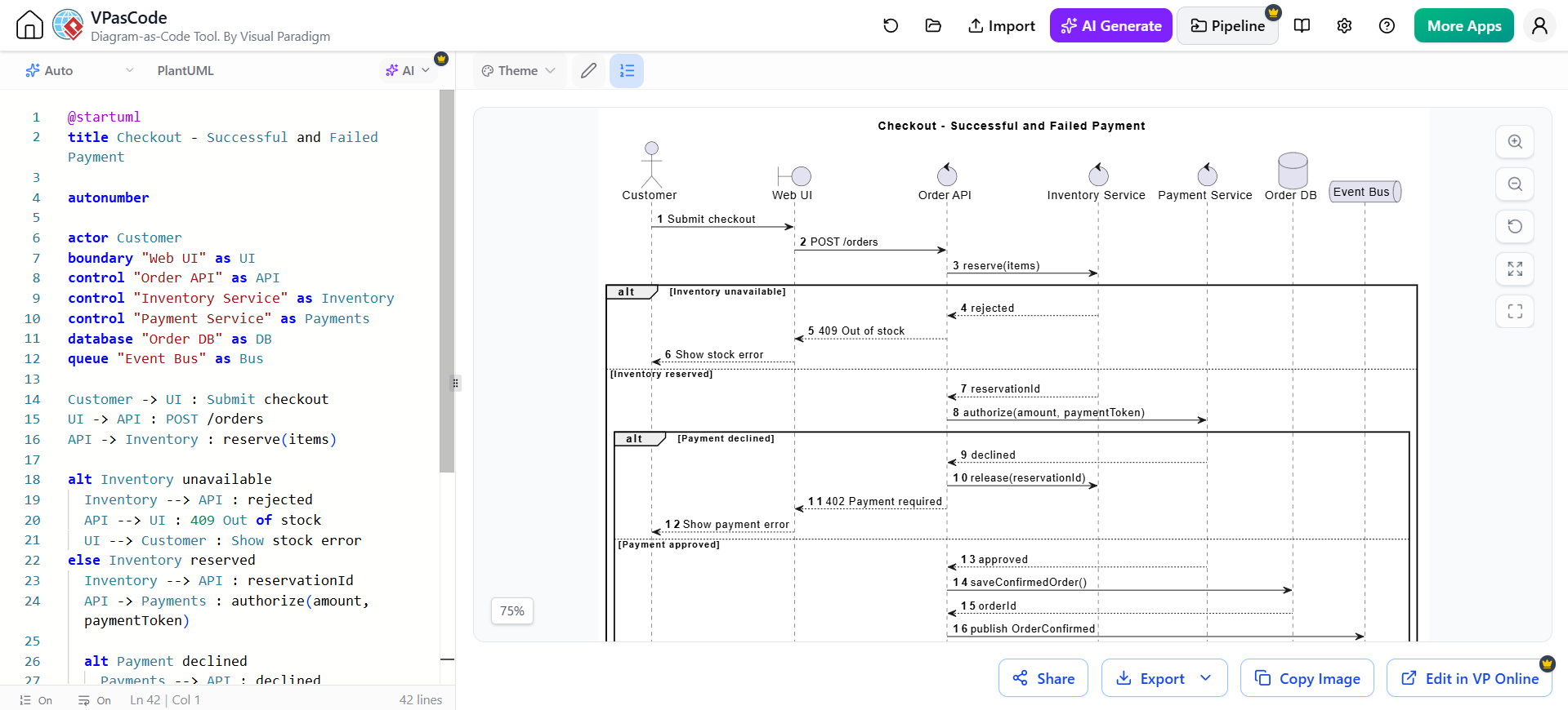
@startuml
title Checkout - Successful and Failed Payment

autonumber

actor Customer
boundary "Web UI" as UI
control "Order API" as API
control "Inventory Service" as Inventory
control "Payment Service" as Payments
database "Order DB" as DB
queue "Event Bus" as Bus

Customer -> UI : Submit checkout
UI -> API : POST /orders
API -> Inventory : reserve(items)

alt Inventory unavailable
  Inventory --> API : rejected
  API --> UI : 409 Out of stock
  UI --> Customer : Show stock error
else Inventory reserved
  Inventory --> API : reservationId
  API -> Payments : authorize(amount, paymentToken)

  alt Payment declined
    Payments --> API : declined
    API -> Inventory : release(reservationId)
    API --> UI : 402 Payment required
    UI --> Customer : Show payment error
  else Payment approved
    Payments --> API : approved
    API -> DB : saveConfirmedOrder()
    DB --> API : orderId
    API -> Bus : publish OrderConfirmed
    API --> UI : 201 Created(orderId)
    UI --> Customer : Show confirmation
  end
end

@enduml
A useful sequence diagram normally contains:
-
External actors
-
UI or API boundary
-
Controllers or application services
-
Domain services
-
Databases
-
Message brokers
-
External systems
-
Success and failure paths
Avoid turning a sequence diagram into source code. It should show meaningful interactions and ownership, not every getter, local variable, or framework call.
A sequence diagram and a communication diagram are semantically related; sequence diagrams are usually preferable because they make temporal order immediately visible.
Step 4: Stabilize the domain with a class diagram
A class diagram is useful when the team needs a shared vocabulary and an explicit model of relationships. It can describe business concepts, persistence structures, or implementation classes, but do not mix all three levels casually.
For domain modeling, emphasize:
-
Names and responsibilities
-
Associations
-
Multiplicity
-
Ownership
-
Invariants
-
Important value objects
-
Key operations
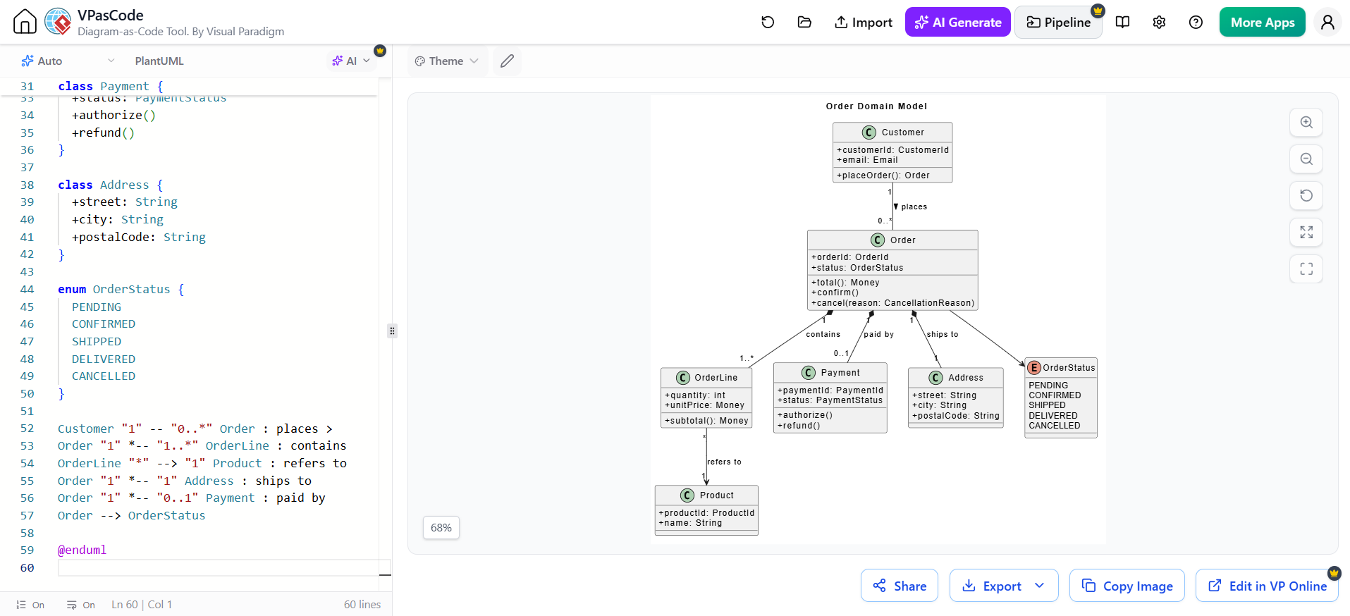
@startuml
title Order Domain Model

skinparam classAttributeIconSize 0

class Customer {
  +customerId: CustomerId
  +email: Email
  +placeOrder(): Order
}

class Order {
  +orderId: OrderId
  +status: OrderStatus
  +total(): Money
  +confirm()
  +cancel(reason: CancellationReason)
}

class OrderLine {
  +quantity: int
  +unitPrice: Money
  +subtotal(): Money
}

class Product {
  +productId: ProductId
  +name: String
}

class Payment {
  +paymentId: PaymentId
  +status: PaymentStatus
  +authorize()
  +refund()
}

class Address {
  +street: String
  +city: String
  +postalCode: String
}

enum OrderStatus {
  PENDING
  CONFIRMED
  SHIPPED
  DELIVERED
  CANCELLED
}

Customer "1" -- "0..*" Order : places >
Order "1" *-- "1..*" OrderLine : contains
OrderLine "*" --> "1" Product : refers to
Order "1" *-- "1" Address : ships to
Order "1" *-- "0..1" Payment : paid by
Order --> OrderStatus

@enduml
Use multiplicities deliberately:
-
1means exactly one. -
0..1means optional. -
0..*means zero or more. -
1..*means one or more.
Use composition only when the part’s lifecycle is owned by the whole. For example, an Order can compose its OrderLine objects. Do not use composition merely because two classes are related.
Keep class diagrams readable by creating separate views:
-
Domain overview
-
Persistence model
-
Application services
-
Integration model
-
One bounded context or module at a time
A class diagram should not attempt to display every class in the codebase. For implementation-level detail, generate or reverse-engineer a focused view and keep it separate from the conceptual domain model.
Step 5: Describe architecture with a component diagram
Component diagrams show major replaceable or deployable units and their interfaces. They are more useful for architecture than a huge class diagram. They can represent monolith modules, microservices, libraries, adapters, or external systems.
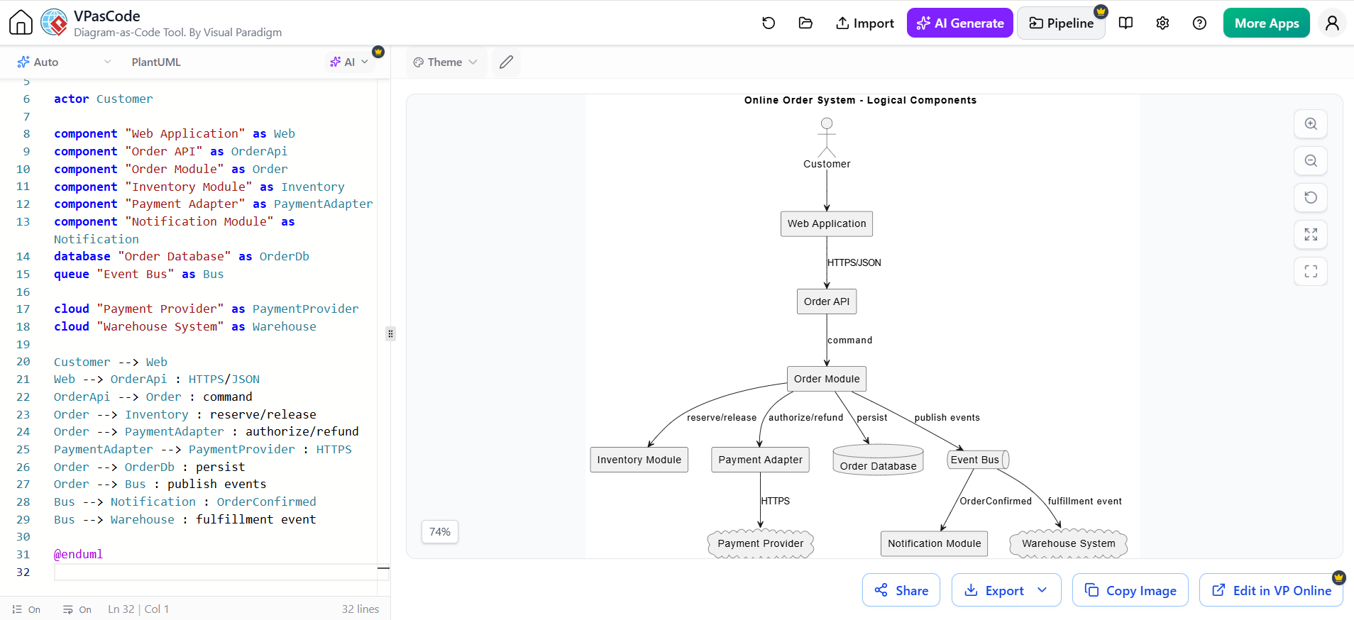
@startuml
title Online Order System - Logical Components

skinparam componentStyle rectangle

actor Customer

component "Web Application" as Web
component "Order API" as OrderApi
component "Order Module" as Order
component "Inventory Module" as Inventory
component "Payment Adapter" as PaymentAdapter
component "Notification Module" as Notification
database "Order Database" as OrderDb
queue "Event Bus" as Bus

cloud "Payment Provider" as PaymentProvider
cloud "Warehouse System" as Warehouse

Customer --> Web
Web --> OrderApi : HTTPS/JSON
OrderApi --> Order : command
Order --> Inventory : reserve/release
Order --> PaymentAdapter : authorize/refund
PaymentAdapter --> PaymentProvider : HTTPS
Order --> OrderDb : persist
Order --> Bus : publish events
Bus --> Notification : OrderConfirmed
Bus --> Warehouse : fulfillment event

@enduml
A component diagram should make these decisions visible:
-
Which component owns a capability?
-
Which component owns data?
-
Which interfaces are public?
-
Which dependencies are synchronous?
-
Which interactions are asynchronous?
-
Where are external systems isolated behind adapters?
-
Which dependencies are forbidden?
For larger systems, add interface contracts as notes or separate API documentation. Do not encode every endpoint into the architecture diagram.
Step 6: Show runtime topology with a deployment diagram
Create a deployment diagram when location and runtime environment matter. It should show nodes, containers or processes, artifacts, communication paths, and significant external dependencies.
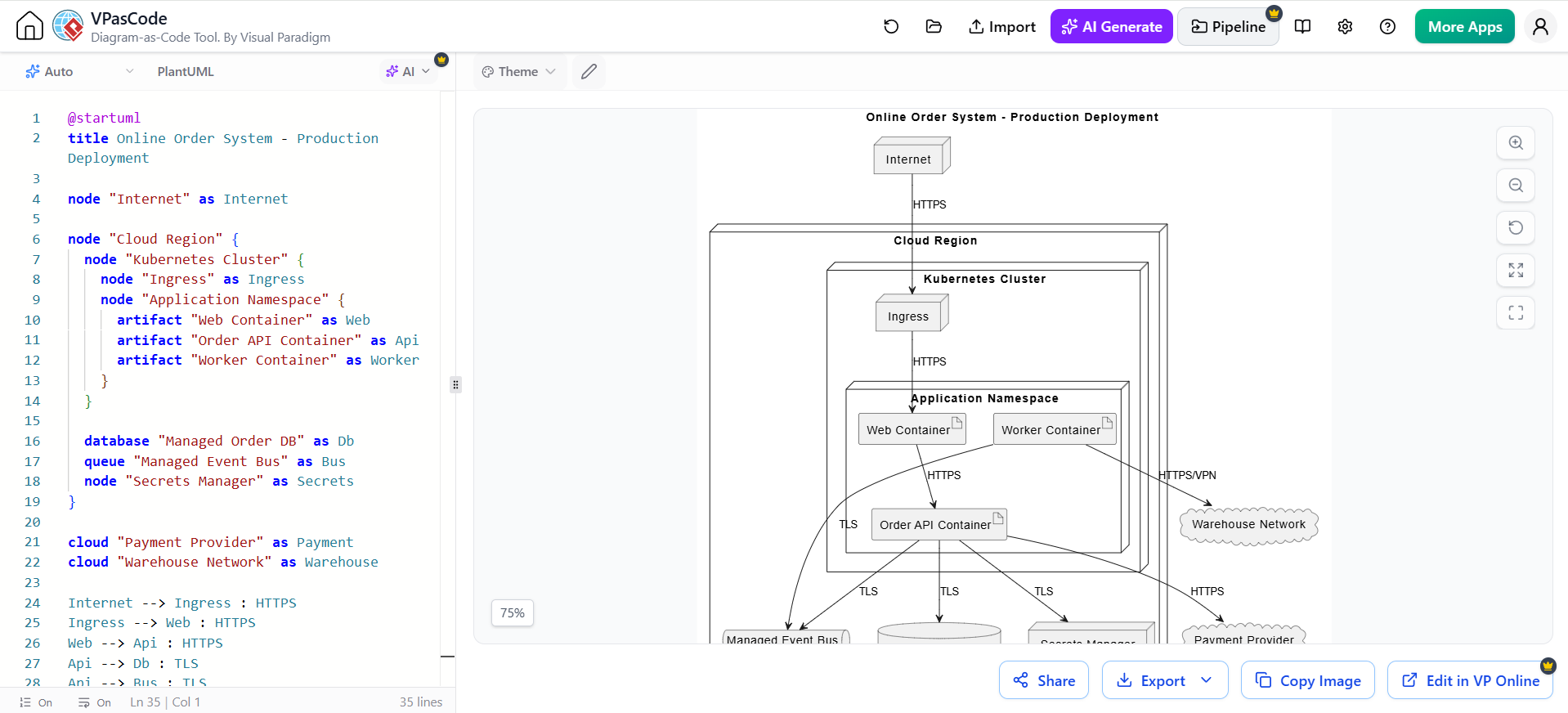
@startuml
title Online Order System - Production Deployment

node "Internet" as Internet

node "Cloud Region" {
  node "Kubernetes Cluster" {
    node "Ingress" as Ingress
    node "Application Namespace" {
      artifact "Web Container" as Web
      artifact "Order API Container" as Api
      artifact "Worker Container" as Worker
    }
  }

  database "Managed Order DB" as Db
  queue "Managed Event Bus" as Bus
  node "Secrets Manager" as Secrets
}

cloud "Payment Provider" as Payment
cloud "Warehouse Network" as Warehouse

Internet --> Ingress : HTTPS
Ingress --> Web : HTTPS
Web --> Api : HTTPS
Api --> Db : TLS
Api --> Bus : TLS
Worker --> Bus : TLS
Api --> Secrets : TLS
Api --> Payment : HTTPS
Worker --> Warehouse : HTTPS/VPN

@enduml
Keep deployment diagrams concerned with runtime concerns:
-
Hosts or nodes
-
Containers and processes
-
Network boundaries
-
Databases and queues
-
External providers
-
Protocols
-
Trust zones
-
Replication or failover, when relevant
Do not use a deployment diagram as a substitute for infrastructure-as-code. The diagram communicates architecture; Terraform, Kubernetes manifests, and deployment configuration remain the executable source of infrastructure truth.
Step 7: Add state machines for lifecycle-heavy entities
A state machine is worthwhile when behavior depends on the current state and invalid transitions must be prevented. State diagrams model permitted states and the events that cause transitions.
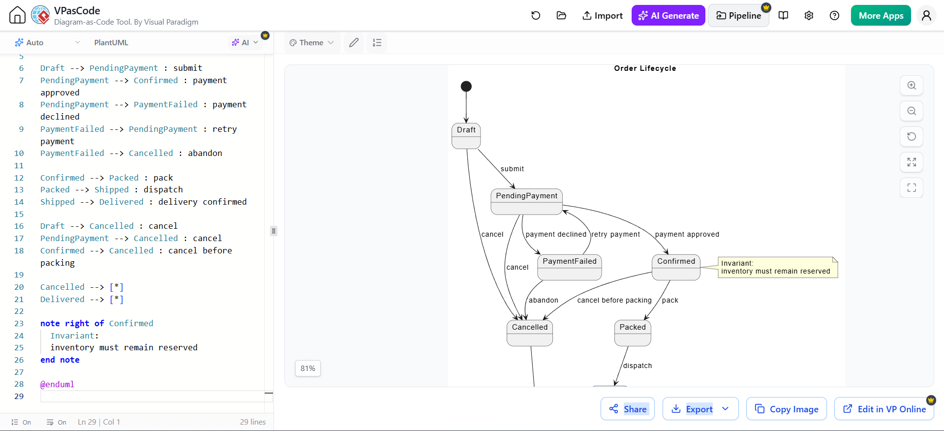
@startuml
title Order Lifecycle

[*] --> Draft

Draft --> PendingPayment : submit
PendingPayment --> Confirmed : payment approved
PendingPayment --> PaymentFailed : payment declined
PaymentFailed --> PendingPayment : retry payment
PaymentFailed --> Cancelled : abandon

Confirmed --> Packed : pack
Packed --> Shipped : dispatch
Shipped --> Delivered : delivery confirmed

Draft --> Cancelled : cancel
PendingPayment --> Cancelled : cancel
Confirmed --> Cancelled : cancel before packing

Cancelled --> [*]
Delivered --> [*]

note right of Confirmed
  Invariant:
  inventory must remain reserved
end note

@enduml
Use a state machine when you have:
-
Many states
-
Explicit transition events
-
Guards or permissions
-
Timeouts
-
Retry behavior
-
State-specific commands
-
Compliance or audit requirements
Do not create one for every database status column. A simple status field does not automatically justify a state model.
4. How the diagrams fit together
The diagrams should form a traceable chain rather than a collection of unrelated pictures.
| Source | Leads to | Validation question |
|---|---|---|
| Use case | Activity diagram | Does the workflow fulfill the user goal? |
| Activity diagram | Sequence diagram | Do system interactions implement each important step? |
| Sequence diagram | Component diagram | Do the required participants and interfaces exist? |
| Class diagram | Sequence diagram | Are messages backed by sensible responsibilities and concepts? |
| Component diagram | Deployment diagram | Can each runtime component be deployed somewhere appropriate? |
| State diagram | Activity and sequence diagrams | Do commands and events respect lifecycle rules? |
A practical traceability scheme is:
-
UC-01 Place Order -
WF-01 Checkout Workflow -
SD-01 Successful Checkout -
SD-02 Payment Failure -
DM-01 Order Domain -
CMP-01 Logical Components -
DEP-01 Production Deployment -
SM-01 Order Lifecycle
Put the identifier in the diagram title and in the related requirements, tests, ADRs, and tickets.
5. What to leave out by default
These UML diagrams are useful but usually not part of the minimum set:
-
Object diagrams: Use for a particular runtime snapshot or test fixture.
-
Communication diagrams: Use when collaboration structure matters more than time order.
-
Package diagrams: Use for very large codebases or dependency governance.
-
Timing diagrams: Use for real-time, embedded, or strict timing behavior.
-
Interaction-overview diagrams: Use when coordinating many interactions.
-
Composite-structure diagrams: Use for complex internal ports and collaborations.
-
Profile diagrams: Use only when defining a UML extension or domain-specific modeling language.
Visual Paradigm supports these broader UML diagram types, as well as database, business-process, and documentation capabilities; the recommendation here is to use them selectively rather than banning them.
Also distinguish UML from neighboring notations:
-
Use BPMN when business-process semantics, events, pools, lanes, and process automation are central.
-
Use ERD for relational database structure.
-
Use C4 when you want a lightweight architecture communication model.
-
Use wireframes for user-interface layout.
-
Use ADRs for architectural decisions and trade-offs.
-
Use OpenAPI, JSON Schema, or event schemas for machine-readable contracts.
UML is not required to represent every kind of project knowledge.
6. Visual Paradigm workflow
Use Visual Paradigm Desktop or Online when you need a model repository, graphical editing, relationship navigation, code engineering, documentation, team collaboration, or traceability. Visual Paradigm provides UML diagramming together with features such as code engineering, database modeling, documentation production, and collaborative modeling, depending on edition and configuration.
A practical Visual Paradigm workflow is:
-
Create a project and establish naming conventions.
-
Create a package or folder for:
-
Requirements
-
Use cases
-
Workflows
-
Interactions
-
Domain model
-
Architecture
-
Deployment
-
-
Create the use case model.
-
Add textual use-case specifications.
-
Refine priority use cases into activity diagrams.
-
Create sequence diagrams for risky or integration-heavy scenarios.
-
Build a focused conceptual class model.
-
Create component and deployment views.
-
Link diagrams to requirements, tests, design decisions, and documentation where your edition supports it.
-
Generate a project specification or publish selected views.
-
Review diagrams with the people who use them; do not treat modeling as a solitary drawing exercise.
Use the graphical environment when semantic modeling, traceability, or collaborative repository management matters more than text-based version control.
7. VPasCode and PlantUML workflow
VPasCode is well suited to diagram-as-code: write PlantUML text, preview it in real time, refine it, and export the result. Its documented support includes use case, class, sequence, activity, component, deployment, state, timing, ERD, and other diagram types. It also supports multiple text-to-diagram engines and browser-based editing.
Use VPasCode when you want:
-
Diagrams stored beside Markdown and source code
-
Pull-request review of diagram changes
-
Repeatable rendering
-
Fast iteration
-
AI-generated starting points
-
SVG, PNG, or PDF export
-
A single text source rather than manually positioned shapes
A useful repository layout is:
docs/
  uml/
    use-cases/
      uc-place-order.puml
    workflows/
      wf-checkout.puml
    sequences/
      sd-checkout-success.puml
      sd-checkout-payment-failure.puml
    domain/
      dm-order.puml
    architecture/
      cmp-order-system.puml
      dep-production.puml
    state/
      sm-order-lifecycle.puml
  adr/
  api/
Add a short header to each file:
@startuml
' ID: SD-01
' Title: Checkout - successful payment
' Owner: Commerce Team
' Status: Accepted
' Updated: 2026-09-27
' Related: UC-01, WF-01, ADR-003
...
@enduml
Treat the .puml file as the source of truth and generated PNG/SVG files as build artifacts unless your documentation pipeline requires committed images.
8. AI-assisted modeling workflow
Use an AI chatbot as a modeling assistant, not as the authority on your system.
Good uses
Ask AI to:
-
Extract actors and goals from requirements.
-
Identify candidate use cases.
-
Convert a use-case narrative into an activity diagram.
-
Generate a first sequence diagram for a scenario.
-
Suggest missing error paths.
-
Detect inconsistent names.
-
Review multiplicities and state transitions.
-
Explain a diagram to a nontechnical audience.
-
Convert a diagram between PlantUML and Mermaid.
-
Produce PlantUML source that you can edit and review.
VPasCode documents AI-assisted diagram generation and refinement, including generating diagram code from natural-language prompts and opening generated diagrams for further editing.
Poor uses
Do not accept AI output without checking:
-
Invented services or requirements
-
Incorrect business rules
-
Missing failure paths
-
Wrong ownership of data
-
Invalid UML or PlantUML syntax
-
Inconsistent terminology
-
Security assumptions
-
False claims about existing APIs or infrastructure
-
Diagrams that look plausible but do not match the code
A strong prompt template
Create a PlantUML sequence diagram.

System: online order system
Scenario: customer checks out with an approved card
Participants: Customer, Web UI, Order API, Inventory Service,
Payment Provider, Order DB, Event Bus
Required behavior:
1. Validate the cart.
2. Reserve inventory.
3. Authorize payment.
4. Persist the confirmed order.
5. Publish OrderConfirmed.
6. Return the order ID.

Also include:
- an alternative for unavailable inventory
- an alternative for declined payment
- release inventory after payment failure
- autonumbering
- no implementation-level getters or framework details

After the diagram, list assumptions and unresolved questions.
Then ask follow-up questions such as:
-
“Which messages are synchronous?”
-
“Who owns the transaction?”
-
“What happens if the event is published twice?”
-
“What is the retry policy?”
-
“Which state transitions are invalid?”
-
“Does the class model support every message in the sequence?”
-
“Does the deployment model contain every runtime participant?”
9. Modeling standards that keep diagrams useful
Keep one abstraction level per diagram
Do not place business goals, Java classes, Kubernetes pods, and database columns on the same diagram unless the purpose explicitly requires it.
Prefer:
-
Conceptual domain model
-
Logical component model
-
Physical deployment model
as separate views.
Limit diagram size
As a starting point:
-
Use case diagram: roughly 5–15 use cases
-
Sequence diagram: one scenario, usually fewer than 10–12 lifelines
-
Class diagram: one domain area or bounded context
-
Component diagram: major components, not every class
-
Deployment diagram: significant nodes and communication paths
Split a diagram when the reader must zoom out to understand it.
Name consistently
Use a shared glossary:
-
Order, not sometimesPurchaseand sometimesTransaction -
Payment Provider, not sometimesCard Gateway -
OrderConfirmed, not sometimesOrderCreatedif they mean different events
Use nouns for entities and verbs for actions.
Show failure paths
Happy-path-only models create false confidence. For important scenarios, include:
-
Validation failure
-
Authorization failure
-
Timeout
-
Duplicate request
-
Missing data
-
Partial failure
-
Retry
-
Compensation
-
Cancellation
Model decisions, not decoration
Every element should help answer a question. Remove:
-
Decorative icons
-
Redundant arrows
-
Unused attributes
-
Framework-specific detail
-
Repeated labels
-
Relationships with no semantic meaning
Review diagrams like code
For every change, ask:
-
Does the diagram render?
-
Does it match the requirement?
-
Does it match the implementation?
-
Are names consistent?
-
Are error paths represented?
-
Is the abstraction level appropriate?
-
Is the diagram still readable?
-
Should a related diagram or test change too?
10. A lightweight definition of done
A feature is sufficiently modeled when:
-
Its user goal and system boundary are clear.
-
The main workflow and important alternatives are documented.
-
At least one risky or integration-heavy scenario has a sequence diagram.
-
The key domain concepts and ownership are understood.
-
Component boundaries and interfaces are clear where architecture matters.
-
Runtime deployment is documented when infrastructure affects behavior.
-
Lifecycle rules are explicit for stateful entities.
-
Diagram identifiers link the views to requirements, tests, decisions, or code.
-
A domain expert and an implementer can both explain the diagrams.
-
The diagrams are small enough to maintain.
The central principle is simple: use the smallest set of diagrams that makes the next engineering decision unambiguous. For most teams, that means use cases, activities, sequences, classes, components, and deployments—with state machines added only where lifecycle behavior genuinely deserves its own model.
PlantUML support and workflow references
PlantUML supports the core UML types used in this guide, including sequence, use case, class, activity, component, deployment, and state diagrams.
Summary
Most software projects can be modeled effectively with a focused set of UML diagrams:
- Use case diagrams define system scope, actors, and user goals.
- Activity diagrams describe workflows, decisions, responsibilities, and parallel work.
- Sequence diagrams show how users, services, components, and external systems collaborate over time.
- Class diagrams establish the domain vocabulary, relationships, and responsibilities.
- Component diagrams clarify architectural boundaries, interfaces, dependencies, and ownership.
- Deployment diagrams show where software runs and how runtime infrastructure is connected.
- State-machine diagrams capture lifecycle rules for entities with meaningful states and transitions.
These diagrams should be created selectively and connected through traceable identifiers, such as linking a use case to its workflow, sequence diagrams, domain model, architecture, and tests. The goal is a coherent set of views rather than a collection of isolated illustrations.
Visual Paradigm is well suited to structured graphical modeling, documentation, traceability, and collaboration. VPasCode and PlantUML are particularly effective when diagrams should be stored as text, reviewed through version control, generated repeatedly, or maintained alongside application code. AI chatbots can help extract requirements, generate PlantUML drafts, identify missing scenarios, and review consistency, but every result must be checked by the project team.
The most important principle is to model only what supports communication and decision-making. A diagram is successful when it makes a requirement, workflow, design choice, architectural boundary, or operational assumption easier to understand—not simply when it contains valid UML notation.




 English
 Arabic
 Chinese (Simplified)
 Dutch
Dutch French
 German
 Italian
 Japanese
 Korean
 Portuguese
 Russian
 Spanish