


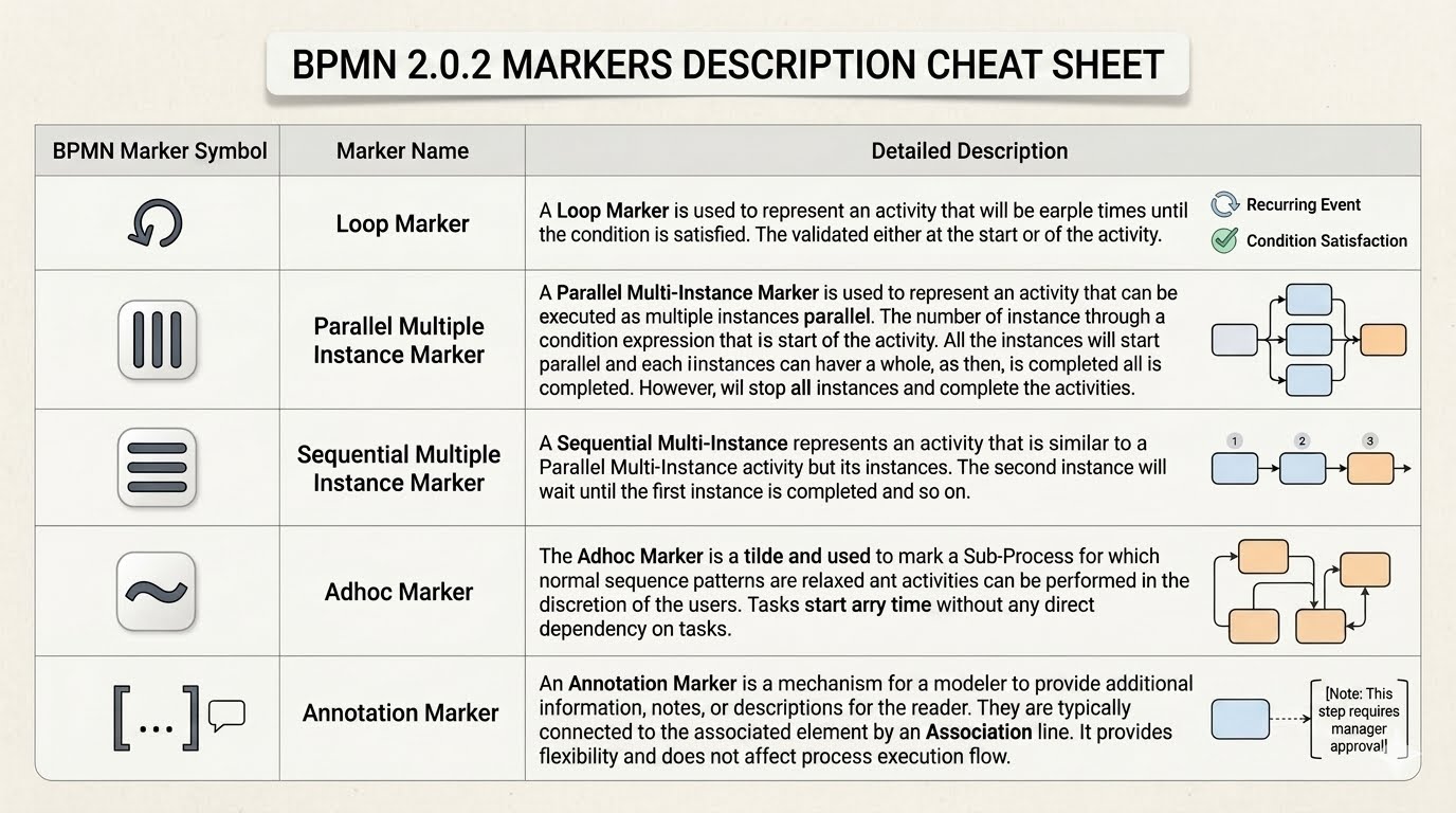
Business Process Model and Notation (BPMN) is the global standard for visualizing business processes. While most beginners quickly learn the basics of tasks, gateways, and events, they often overlook Markers. These small but powerful symbols act as “modifiers” that sit inside an activity shape to fundamentally change how that task behaves.
Without markers, a process diagram might look correct structurally but fail to capture critical execution logic—such as whether a task repeats, runs in parallel, or allows human discretion. This guide breaks down the five essential BPMN 2.0.2 markers, provides real-world context, and demonstrates how to implement them efficiently using Visual Paradigm and its AI-assisted modeling features.
The Role of Markers in BPMN
In the BPMN 2.0 specification, markers are visual indicators placed inside the “body” of an activity (like a Task or a Sub-Process). They do not represent a new shape, but rather a specific behavior or lifecycle for that shape. They answer the question: “How does this specific activity interact with the process flow?”
There are five primary markers you need to master to move from basic flowcharting to professional business process modeling:
- Loop Marker: Repetition logic.
- Parallel Multi-Instance Marker: Concurrent execution.
- Sequential Multi-Instance Marker: Ordered repetition.
- Adhoc Marker: Flexible, user-driven execution.
- Annotation Marker: Data documentation.
1. The Loop Marker
The Loop Marker is used to represent an activity that will repeat a certain number of times until a specific condition is satisfied. It is the standard way to model iteration without cluttering the diagram with complex gateway loops.
How it works:
- The marker appears as a curved arrow.
- It is typically paired with a Condition Expression (e.g., “Is data valid?”).
- If the condition is true, the activity executes again; if false, the flow exits.
Real-World Context: Imagine a data validation task. The system processes a file. If the file contains errors, it must loop back to the “Fix Errors” task. Once the file is clean, the process continues to “Archive”.
Implementation in Visual Paradigm
When using Visual Paradigm, you can apply the Loop Marker to a Task by right-clicking the element, selecting Edit Marker, and enabling the Loop option. You can then define the Loop Condition directly within the element’s properties dialog.
2. Parallel Multi-Instance Marker
The Parallel Multi-Instance Marker is used when an activity needs to be executed multiple times simultaneously (concurrently). This is visually represented by three vertical lines inside the activity shape.
How it works:
- Input Data: Usually an array or list of items (e.g., a list of 50 invoices).
- Execution: The process spawns multiple instances of the task to process these items in parallel.
- Completion: The process waits until all instances are finished before proceeding.
Real-World Context: An Order Fulfillment center receives an order for 20 distinct items. Instead of packing them one by one (sequential), the system assigns 20 packers to work on the items simultaneously. The order is only “Complete” when all 20 items are packed.
Implementation in Visual Paradigm
To implement this in Visual Paradigm, select your Task and enable the Multi-Instance property. Set the Execution Type to Parallel. You must also define the Loop Cardinality (e.g., ${items.size} or a specific number) to tell the engine how many instances to create.
3. Sequential Multi-Instance Marker
A Sequential Multi-Instance Marker represents an activity that is similar to a Parallel Multi-Instance activity, but the instances execute one after another. This is visually represented by three horizontal lines inside the activity shape.
How it works:
- Execution: The task runs the first instance. Only after that is complete does it start the second instance, and so on.
- Blocking: Unlike parallel execution, this creates a bottleneck for time.
Real-World Context: Consider a manual review process for visa applications. Even if you have 100 applications, a single officer might be assigned to review them one by one. You cannot process the 50th application until the 49th is signed off.
Implementation in Visual Paradigm
In Visual Paradigm, set the Multi-Instance property to Sequential. This is crucial for modeling processes where resources are limited or where strict ordering is mandated by business policy.
4. The Adhoc Marker
The Adhoc Marker (represented by a tilde symbol ~) is one of the most powerful features for modeling complex human behaviors. It marks a Sub-Process for which normal sequence patterns are relaxed, and activities can be performed in the discretion of the users.
How it works:
- No Dependencies: Tasks inside an Adhoc Sub-Process do not require strict entry/exit conditions.
- Flexibility: Tasks can be started any time and in any order.
- Completion: The sub-process completes when the user decides to end it.
Real-World Context: A “Troubleshooting” phase in IT support. A technician might reboot the server, check logs, or restart the service. There is no fixed order. The phase ends only when the problem is resolved and the ticket is closed.
Implementation in Visual Paradigm
In Visual Paradigm, create a Sub-Process and set the Adhoc property. This allows you to draw connections between tasks inside the sub-process without enforcing strict sequence flows, perfectly modeling the “Adhoc” nature of human problem-solving.
5. The Annotation Marker
The Annotation Marker is a mechanism for a modeler to provide additional information, notes, or descriptions for the reader. It does not affect process execution flow but is vital for documentation.
How it works:
- It is typically connected to an associated element by an Association line.
- It provides flexibility for adding rules, constraints, or approval requirements without changing the diagram’s geometry.
Real-World Context: A “Manager Approval” task might need a note stating, “This step requires approval for amounts over $5,000.” This annotation clarifies the logic without needing a complex decision gateway.
Tooling: Visual Paradigm for Efficient Modeling
Mastering these markers requires a tool that supports the BPMN 2.0 specification natively. Visual Paradigm is a robust modeling tool that simplifies the application of these markers.
Why Visual Paradigm?
- Drag-and-Drop Markers: Instead of manually drawing lines or adding shapes, Visual Paradigm provides a dedicated “Marker” palette. You can simply drag a Loop or Multi-Instance icon onto a task.
- Property Dialogs: The tool offers a centralized properties window to define loop conditions, cardinality expressions, and adhoc rules, reducing syntax errors.
- AI-Assisted Modeling: With Visual Paradigm‘s AI features, you can describe a process in natural language (e.g., “Create a process where tasks repeat until valid”), and the tool can automatically apply the correct Loop Markers and structures.
Step-by-Step: Adding a Loop Marker in Visual Paradigm
- Open your Diagram: Launch Visual Paradigm and open your BPMN diagram.
- Select the Task: Click on the Task (Activity) you wish to modify.
- Open Properties: Press
Ctrl + Shift + Por right-click and select Properties. - Enable Loop: Navigate to the Marker section. Check the box for Loop.
- Define Condition: In the expression field, enter your logic (e.g.,
isValid == false). - Apply: Click OK. The marker icon will appear on your diagram.
By leveraging the features within Visual Paradigm, you ensure your diagrams are not just visual representations, but executable logic that accurately reflects your business rules.

 English
 Arabic
 Chinese (Simplified)
 Dutch
Dutch French
 German
 Italian
 Japanese
 Korean
 Portuguese
 Russian
 Spanish