


In the world of software architecture, communication is everything. Before writing a single line of code, architects must visualize how a system fits into the broader world. The C4 Model provides a standardized way to do this, breaking architecture down into four hierarchical levels. We begin at the top with Level 1: The System Context Diagram.
What is a System Context Diagram?
A System Context Diagram provides the “30,000-foot view” of your software. It defines the boundaries of your system and identifies the people (actors) and external systems that interact with it. It answers the fundamental question: “What does this system do, and who uses it?”
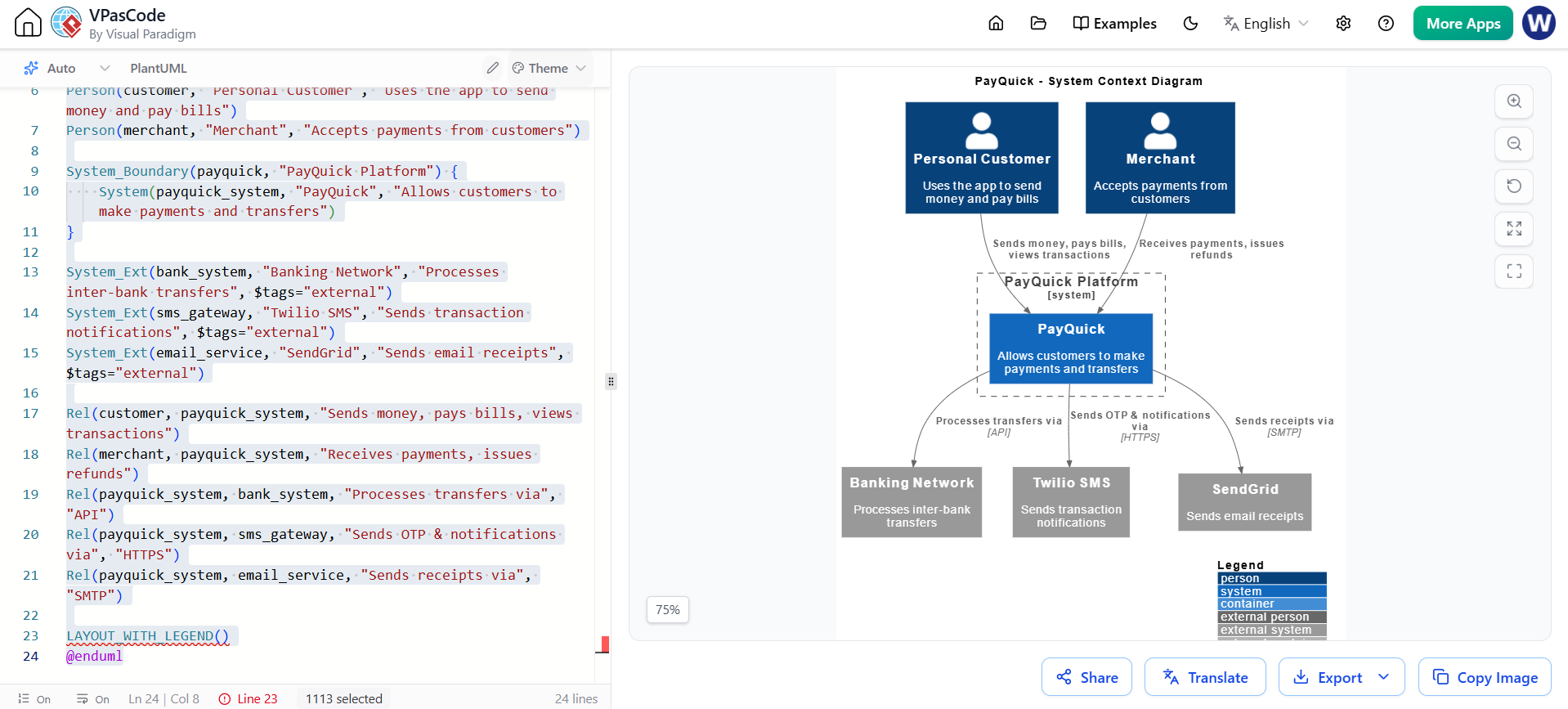
In this tutorial, we will deconstruct the architecture of PayQuick, a modern online payment platform, using the C4 Model and PlantUML.
Key Components of the Diagram
Based on the PayQuick example, a robust System Context Diagram must define three specific types of elements:
- Person (Actors): The human users interacting with the system. In PayQuick, these are the Personal Customer and the Merchant.
- System (The Core): The software you are building. Here, it is the PayQuick Platform.
- External Systems: Third-party services your system relies on. PayQuick integrates with Banking Networks, SMS Gateways, and Email Services.
Step-by-Step: Modeling the PayQuick Architecture
To create this diagram, we use PlantUML, a text-to-diagram tool that is the industry standard for C4 modeling. The syntax is intuitive: we define the actors, draw the system boundary, and then connect them with relationships.
1. Defining the Actors
First, we declare the humans involved. We assign them unique IDs (like customer and merchant) and descriptive labels.
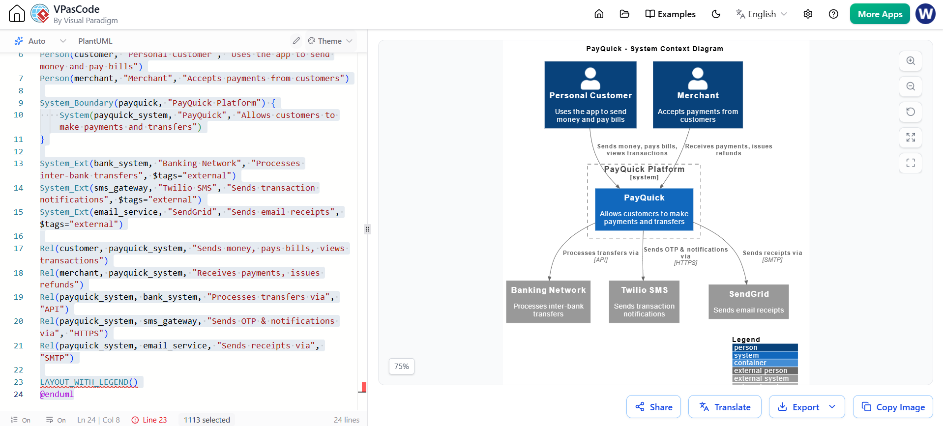
Person(customer, "Personal Customer", "Uses the app to send money and pay bills")
Person(merchant, "Merchant", "Accepts payments from customers")
2. Defining the System Boundary
Next, we encapsulate our application. The SystemBoundary tag creates the visual box that separates your internal logic from the outside world.
System_Boundary(payquick, "PayQuick Platform") {
    System(payquick_system, "PayQuick", "Allows customers to make payments and transfers")
}
3. Defining External Systems
Our payment system doesn’t exist in a vacuum. It needs to talk to the real world. We define these as SystemExt (External Systems) and assign them tags to ensure they are rendered differently in the diagram.
System_Ext(bank_system, "Banking Network", "Processes inter-bank transfers", $tags="external")
System_Ext(sms_gateway, "Twilio SMS", "Sends transaction notifications", $tags="external")
System_Ext(email_service, "SendGrid", "Sends email receipts", $tags="external")
4. Establishing Relationships
Finally, we draw the lines. The Rel command connects the entities. Crucially, you should label the relationship with a verb (e.g., “Sends money”, “Processes transfers”) to describe the flow of data.
Rel(customer, payquick_system, "Sends money, pays bills, views transactions")
Rel(merchant, payquick_system, "Receives payments, issues refunds")
Rel(payquick_system, bank_system, "Processes transfers via", "API")
Rel(payquick_system, sms_gateway, "Sends OTP & notifications via", "HTTPS")
Rel(payquick_system, email_service, "Sends receipts via", "SMTP")Why Start Here?
Developers often rush straight to the code, but a System Context Diagram prevents “scope creep.” By visualizing the PayQuick platform alongside the Banking Network and SMS Gateway, stakeholders can immediately see that the payment logic is internal, but the actual money movement is handled by the Banking Network.
This diagram serves as the single source of truth for your project’s scope, ensuring that everyone—from the CEO to the junior developer—understands exactly what the system is responsible for.

 English
 Arabic
 Chinese (Simplified)
 Dutch
 French
 German
 Italian
 Japanese
 Korean
 Portuguese
 Russian
 Spanish