


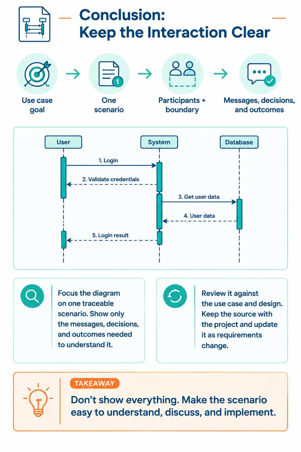
In the world of software architecture and system design, clarity is currency. When teams attempt to document how different components of a system communicate, they often fall into the trap of creating overwhelming, monolithic diagrams that obscure rather than illuminate. Based on industry best practices and the powerful capabilities of Visual Paradigm, this tutorial explores how to create a high-value Sequence Diagram that focuses on a single, traceable scenario.
The Core Philosophy: Contextual Modeling
The most effective modeling approach starts with a question, not a diagram. Instead of asking “How does the system work?”, ask “What happens when a user logs in?” or “How does the system handle a payment failure?”. By anchoring your modeling effort to a specific question, you naturally limit the scope and ensure the resulting diagram is immediately useful to stakeholders.
To achieve this, you must define the boundaries of your model:
- Participants: Identify the actors involved (e.g., User, System).
- Boundary: Determine what is inside the system and what is outside (e.g., the Database).
- Focus: Select one specific scenario to illustrate.
By strictly adhering to these boundaries, you prevent the diagram from becoming a generic “data dump” and instead turn it into a precise tool for discussion, design reviews, and implementation planning.
Step-by-Step: Constructing a Traceable Sequence Diagram
Visual Paradigm allows for a seamless workflow from sketching to refining. Here is how you can model a “User Login” scenario to demonstrate the flow of messages and data.
1. Define the Lifelines
Begin by identifying the key objects or actors. In a typical login flow, you will need:
- User: The initiator of the interaction.
- System: The application processing the request.
- Database: The external or internal storage holding credentials.
2. Map the Interaction Flow
Sequence diagrams are all about time. Messages flow from left to right and top to bottom. In this scenario, we are tracing a synchronous request followed by asynchronous responses.
- Step 1 (Login): The User sends a login request to the System. This is an active message.
- Step 2 (Validate): The System requests validation from the User (e.g., asking for a password). This is often a return message.
- Step 3 (Get Data): The System queries the Database for user data. This is a call message.
- Step 4 (User Data): The Database returns the requested data to the System. This is a reply message.
- Step 5 (Result): The System sends the final login result back to the User.
3. The “Don’t Show Everything” Rule
A common mistake in sequence diagrams is trying to capture every possible exception or error handling path in a single view. The image provided suggests a crucial takeaway: Don’t show everything. Make the scenario easy to understand, discuss, and implement.
Focus the diagram on one traceable scenario. If you need to show error handling, create a separate diagram or a sub-scenario. By keeping the diagram clean, you ensure that the source of truth remains with the project and is easy to update as requirements change.
Refining with Visual Paradigm
Visual Paradigm’s tooling supports this iterative process. Unlike a one-off drawing, your model should evolve. You can:
- Reuse Model Elements: Copy lifelines or message definitions to ensure consistency across different diagrams.
- Validate: Use the validation tools to ensure your syntax is correct and your flows make logical sense.
- AI-Assisted Features: Start with a draft by using AI to generate the initial structure based on your text description.
Once the diagram is created, bring it into your work. Use it in planning, design reviews, implementation discussions, testing, onboarding, or process improvement. A model is only useful when it stays relevant—not simply because it was completed once.

 English
 Arabic
 Chinese (Simplified)
 Dutch
 French
 German
 Italian
 Japanese
 Korean
 Portuguese
 Russian
 Spanish