


The Activity Diagram helps describe the flow of control of the target system, such as exploring complex business rules and operations, describing use cases, and modeling business processes.
Introduction
Activity diagrams are a fundamental part of the Unified Modeling Language (UML) used to model the dynamic aspects of a system. They focus on the sequence and conditions for coordinating lower-level behaviors, rather than which classifiers own those behaviors. These are commonly called control flow and object flow models.
The behaviors coordinated by these models can be initiated because:
-
Other behaviors finish executing
-
Objects and data become available
-
Events occur external to the flow

visual Paradigm Activity Diagram Tool
Purpose and Applications
Activity diagrams serve multiple modeling purposes:
🔹 Procedural Computation: Activities function as methods corresponding to operations on classes in object-oriented models.
🔹 Business Process Engineering: Applied to organizational modeling for workflow design, where events may originate from inside the system (task completion) or outside (customer interactions).
🔹 Information System Modeling: Used to specify system-level processes and coordinate complex business rules.
🔹 Use Case Elaboration: Help describe the internal flow of operations within a use case scenario.
Sample Activity Diagram
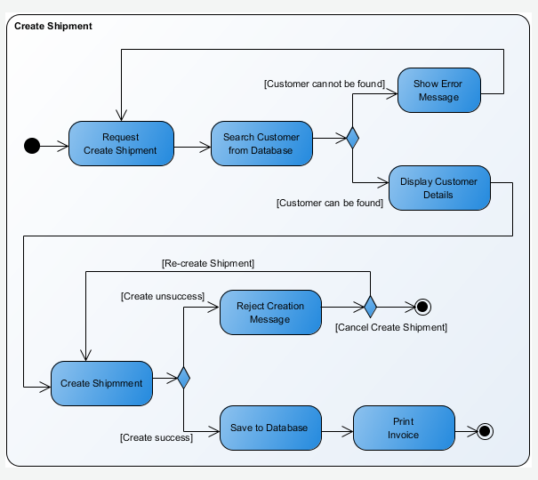
Example of a typical activity diagram showing control flow, decision points, and parallel processing.
Complete Notation Reference
Below is a comprehensive reference of all Activity Diagram notations, including visual icons, definitions, and key properties.
Core Elements
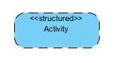
Activity
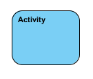
Definition: An activity specifies the coordination of executions of subordinate behaviors, using a control and data flow model. The flow of execution is modeled as activity nodes connected by activity edges.
Key Properties:
| Property | Description |
|---|---|
| Name | The name of the activity |
| Language | Modeling language used |
| Precondition | Constraints that must be fulfilled when invoked |
| Postcondition | Constraints fulfilled after execution completes |
| Single execution | If true, all invocations handled by same execution |
| Read only | If true, activity cannot make non-local changes |
| Reentrant | Whether behavior can be invoked while still executing |
| Parameters | Order and type of arguments for invocation |
Activity Parameter Node
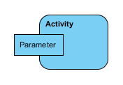
Definition: Object nodes at the beginning and end of flows that provide a means to accept inputs to an activity and provide outputs from the activity, through the activity parameters.
Key Properties:
| Property | Description |
|---|---|
| Parameter | The parameter the node accepts/provides values for |
| Upper bound | Maximum tokens allowed in the node |
| Ordering kind | How tokens are ordered for selection |
| Direction | Indicates if parameter is input or output (default: in) |
| Type | The type of the activity parameter node |
| Must isolate | If true, actions execute in isolation (default: false) |
Action
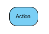
Definition: Represents a single step within an activity that is not further decomposed. An action will not begin execution until all input conditions are satisfied.
Key Properties:
| Property | Description |
|---|---|
| Name | The name of the action |
| Visibility | Accessibility within namespaces |
| Type | Call behavior action or call operation action |
| Effect | The effect of completing the action |
| Must isolate | Isolates effects from actions outside the group |
Event Handling Actions
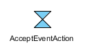
Accept Event Action
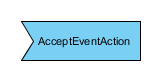
Definition: An action that waits for the occurrence of an event meeting specified conditions.
Accept Time Event Action
Definition: If the occurrence is a time event, the result value contains the time at which the occurrence transpired. Informally called a “wait time action.”
Send Signal Action
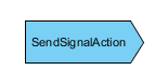
Definition: Creates a signal instance from inputs and transmits it to the target object, potentially causing a state machine transition or activity execution. The requestor continues immediately; replies are ignored.
Control Nodes
Initial Node

Definition: A control node at which flow starts when the activity is invoked. An activity may have more than one initial node.
Activity Final Node

Definition: An activity may have more than one activity final node. The first one reached stops all flows in the activity.
Flow Final Node

Definition: A flow final destroys all tokens that arrive at it. It has no effect on other flows in the activity.
Decision Node

Definition: Accepts tokens on an incoming edge and presents them to multiple outgoing edges. Which edge is traversed depends on evaluation of guards on outgoing edges.
Merge Node

Definition: Brings together multiple alternate flows. Not used to synchronize concurrent flows but to accept one among several alternate flows.
Fork Node

Definition: A control node that splits a flow into multiple concurrent flows. Has one incoming edge and multiple outgoing edges.
Join Node

Definition: A control node that synchronizes multiple flows. Has multiple incoming edges and one outgoing edge.
Object Nodes & Flows
Object Node
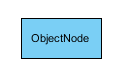
Definition: Indicates an instance of a particular classifier, possibly in a particular state, may be available at a particular point in the activity.
Input Pin

Definition: Object nodes that receive values from other actions through object flows.
Output Pin

Definition: Object nodes that deliver values to other actions through object flows.
Value Pin

Definition: An input pin that provides a value to an action that does not come from an incoming object flow edge.
Central Buffer Node
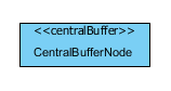
Definition: Accepts tokens from upstream object nodes and passes them along to downstream object nodes. Acts as a buffer for multiple in/out flows. Does not connect directly to actions.
Data Store Node
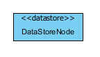
Definition: Represents a persistent storage location for objects within the activity flow.
Control Flow
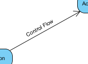
Definition: An edge that starts an activity node after the previous one is finished.
Key Properties:
| Property | Description |
|---|---|
| Source/Target | Nodes connected by the flow |
| Weight | Minimum tokens that must traverse simultaneously |
| Guard | Runtime specification to determine traversability |
Object Flow
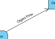
Definition: An activity edge that can have objects or data passing along it.
Key Properties:
| Property | Description |
|---|---|
| Selection | Selects tokens from a source object node |
| Transformation | Changes or replaces data tokens flowing along edge |
| Multicast/Multireceive | Controls object passing methodology |
Structured Activity Nodes
Conditional Node Specification
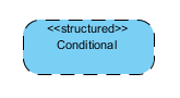
Definition: A structured activity node that represents an exclusive choice among alternatives.
Key Properties:
| Property | Description |
|---|---|
| Assured | If true, at least one test will succeed (default: false) |
| Determinate | If true, at most one test will succeed (default: false) |
| Clauses | Clauses composing the conditional |
| Result | Output pins constituting data flow outputs |
Loop Node
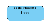
Definition: Represents a loop with setup, test, and body sections. The test section may precede or follow the body section.
Key Properties:
| Property | Description |
|---|---|
| Decider | Output pin whose value determines loop continuation |
| Tested first | If true, test performed before first body execution |
| Setup/Test/Body Parts | Sub-regions for loop components |
| Loop Variables | Values maintained across iterations |
Expansion Region
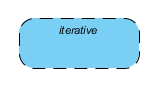
Definition: A strictly nested region with explicit inputs/outputs (modeled as ExpansionNodes). Executed once for each element in the input collection.
Execution Modes:
-
parallel: All interactions are independent
-
iterative: Interactions occur in order of elements
-
stream: A stream of values flows into a single execution
Expansion Node

Definition: An object node used to indicate flow across the boundary of an expansion region. Input collections are broken into individual elements inside; outputs combine elements back into collections.
Sequence Node
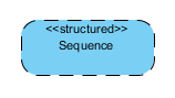
Definition: A structured activity node that executes its actions in order.
Structured Activity Node
Definition: A container node that groups other activity nodes with defined execution semantics.
Advanced Constructs
Interruptible Activity Region
Definition: An activity group that supports termination of tokens flowing in portions of an activity. When a token leaves via interrupting edges, all tokens and behaviors in the region are terminated.
Exception Handler
Definition: Specifies a body to execute if a specified exception occurs during execution of the protected node.
Key Properties:
| Property | Description |
|---|---|
| Protected node | Node protected by the handler |
| Handler body | Node executed if handler catches exception |
| Exception input | Object node receiving the exception token |
| Exception Types | Classifiers of exceptions the handler catches |
Supporting Elements
Swimlane
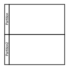
Definition: Used for partitioning children in an activity diagram, typically to show responsibility by actor, department, or system component.
Properties:
-
Horizontal Partitions
-
Vertical Partitions
Note
Definition: A comment that gives the ability to attach remarks to elements. Carries no semantic force but may contain useful modeling information.
Constraint
Definition: A condition or restriction expressed in natural language or machine-readable language for declaring semantics of an element.
Properties:
| Property | Description |
|---|---|
| Name | Optional name of the constraint |
| Expression | Condition that must be true for satisfaction |
Related UML Diagrams
Activity diagrams work best when used alongside other UML diagram types:
| Diagram Type | Purpose | Link |
|---|---|---|
| Use Case Diagram | Capture functional requirements and actor interactions | View |
| Class Diagram | Model static structure and relationships | View |
| Sequence Diagram | Show object interactions over time | View |
| Communication Diagram | Emphasize object relationships in interactions | View |
| State Machine Diagram | Model object states and transitions | View |
| Component Diagram | Show physical components and dependencies | View |
| Deployment Diagram | Model hardware topology and artifact deployment | View |
| Package Diagram | Organize model elements into namespaces | View |
| Object Diagram | Show instances and links at a point in time | View |
| Composite Structure Diagram | Show internal structure of classifiers | View |
| Timing Diagram | Focus on time constraints and state changes | View |
| Interaction Overview Diagram | Combine activity and interaction diagrams | View |
References
- Activity Diagram – Visual Paradigm UML Gallery: Comprehensive reference for UML Activity Diagram notations, definitions, and properties from Visual Paradigm’s official documentation.
- Use Case Diagram – Visual Paradigm UML Gallery: Guide to modeling functional requirements and actor-system interactions using Use Case diagrams.
- Class Diagram – Visual Paradigm UML Gallery: Reference for modeling static structure, classes, attributes, operations, and relationships.
- Sequence Diagram – Visual Paradigm UML Gallery: Documentation for modeling time-ordered interactions between objects and lifelines.
- Communication Diagram – Visual Paradigm UML Gallery: Guide to Collaboration/Communication diagrams emphasizing object links and message flow.
- State Machine Diagram – Visual Paradigm UML Gallery: Reference for modeling states, transitions, events, and actions of individual objects.
- Component Diagram – Visual Paradigm UML Gallery: Documentation for modeling physical components, interfaces, and dependencies in a system.
- Deployment Diagram – Visual Paradigm UML Gallery: Guide to modeling hardware nodes, artifacts, and deployment configurations.
- Package Diagram – Visual Paradigm UML Gallery: Reference for organizing model elements into packages and managing namespaces.
- Object Diagram – Visual Paradigm UML Gallery: Guide to modeling instances of classes and their links at a specific moment.
- Composite Structure Diagram – Visual Paradigm UML Gallery: Documentation for showing internal structure, parts, ports, and connectors of classifiers.
- Timing Diagram – Visual Paradigm UML Gallery: Reference for modeling time-based constraints and state changes across lifelines.
- Interaction Overview Diagram – Visual Paradigm UML Gallery: Guide to combining activity diagram flow control with interaction diagram fragments.
- Object Management Group – UML Specification: Official source for Unified Modeling Language standards and specifications.
- Unified Modeling Language (OMG UML) Superstructure v2.2: Foundational specification defining UML notation semantics, quoted for notation definitions in this guide.
ℹ️ Definition of notations is quoted from Object Management Group Unified Modeling Language (OMG UML) Superstructure Version 2.2 and former versions (for notations that do not exist anymore in latest specification).
This guide is intended for software architects, business analysts, and system designers seeking to model complex workflows and business processes using UML Activity Diagrams. All visual assets and definitions are sourced from Visual Paradigm’s official UML Gallery.
