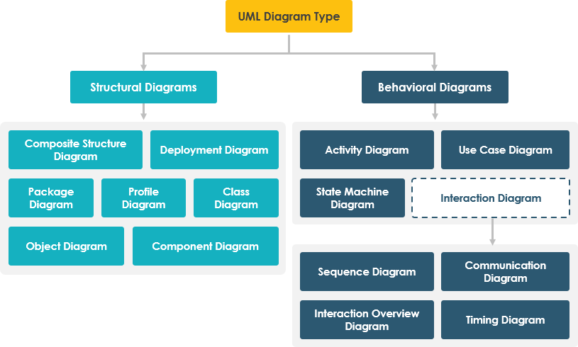
UML (Unified Modeling Language) state machine diagrams are essential tools for modeling the dynamic behavior of individual objects within a system. They provide a clear visualization of an object’s lifecycle, illustrating how it transitions between various states in response to events. These diagrams are particularly valuable in domains such as user interface design, embedded systems, device controllers, and complex business processes where state-dependent behavior plays a critical role.
Key Concepts of UML State Machine Diagrams
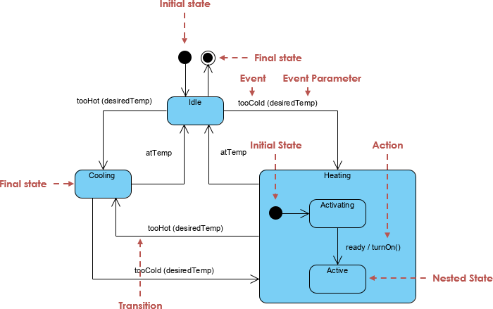
Understanding the foundational elements of a UML state machine diagram is crucial for effective modeling:
-
State: Represented by a rounded rectangle, a state describes the condition of an object at a specific point in time. Examples include
Idle,Processing,Paused, orError. States capture the observable behavior of an object during a period. -
Initial State: Denoted by a black filled circle, this marks the starting point of the object’s lifecycle. It does not represent a state but rather the beginning of the process.
-
Final State: Represented by a filled circle within a larger circle (bullseye), this indicates the end of the object’s lifecycle. Once the system reaches this state, no further transitions occur.
-
Transition: Shown as a solid arrow connecting two states, a transition represents a change from one state to another. Transitions are triggered by specific events.
-
Event/Trigger: The occurrence or action that causes a state transition. Events can be external (e.g., user input) or internal (e.g., timer expiration). For example,
clickSubmitortimeout. -
Guard: A boolean condition that must evaluate to
truefor a transition to occur. Guards are written in square brackets[condition]on the transition arrow. For example:[isValid == true]. -
Action: An executable operation performed during a state transition. Actions can occur on entry (
entry / action), exit (exit / action), or during the transition (event / action). These are atomic computations that modify system behavior. -
Composite State: A state that contains one or more nested sub-states. This allows for hierarchical modeling of complex behaviors. Composite states may include orthogonal regions—parallel sub-states that can be active simultaneously—enabling modeling of concurrent behavior.
Modeling Best Practices
When creating UML state machine diagrams, consider the following:
-
Use meaningful state names that reflect the object’s behavior.
-
Ensure all possible transitions are accounted for to avoid unreachable states.
-
Use guards to prevent invalid transitions and improve model accuracy.
-
Avoid overly complex diagrams by decomposing large state machines into composite states or separate diagrams.
-
Use orthogonal regions when modeling systems with parallel behaviors (e.g., a media player that can be both playing and buffering).
Visual Paradigm: A Powerful UML Modeling Platform
Visual Paradigm (VP) is a comprehensive UML modeling tool that supports the creation, editing, and management of state machine diagrams. It offers a rich set of features designed to streamline the modeling process and improve collaboration across teams.
AI-Powered Diagram Generation
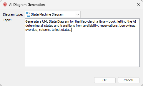
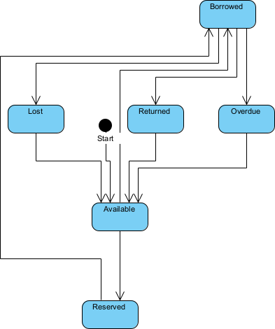
One of the most transformative features of Visual Paradigm is its AI chatbot, accessible via https://chat.visual-paradigm.com/diagram/uml-state-machine-diagram/. Users can describe system behavior in plain English—such as “When the user clicks the start button, the system moves from Idle to Processing, but only if the device is online”—and the AI instantly generates a corresponding UML state machine diagram. This accelerates the initial design phase and lowers the barrier to entry for non-experts.
Conversational Editing & Refinement
The AI chatbot enables conversational editing. Instead of manually redrawing elements, users can interact with the AI to refine diagrams. For instance, you can ask: “Add a ‘Paused’ state between Processing and Idle” or “Add a guard condition that prevents transition if battery level is below 20%.” The AI interprets these requests and updates the diagram accordingly.
Validation & Error Detection
Visual Paradigm’s AI performs real-time analysis of state machine diagrams to detect logical inconsistencies such as:
-
Missing transitions from a state
-
Unreachable states
-
Deadlocks or cycles without exit conditions
-
Inconsistent guard conditions
This automated validation helps maintain diagram integrity and reduces the risk of design flaws.
Design-to-Code Automation
Visual Paradigm supports code generation from UML models. After finalizing a state machine diagram, developers can generate skeleton code in languages like Java, C#, or Python. This feature bridges the gap between design and implementation, ensuring that the code aligns with the intended behavior and reducing manual coding errors.
Documentation Management Integration
Visual Paradigm integrates with OpenDocs, enabling seamless embedding of UML diagrams into technical documentation. This ensures that design artifacts remain synchronized with documentation, promoting consistency and knowledge sharing across teams.
Benefits of Using AI in UML State Machine Modeling
The integration of AI into UML modeling offers several advantages:
-
Reduced Design Time: AI eliminates the need for manual drafting, allowing teams to focus on logic validation rather than syntax.
-
Improved Accuracy: Automated validation catches errors early in the design phase.
-
Enhanced Collaboration: Non-technical stakeholders can contribute by describing behavior in natural language, which the AI translates into diagrams.
-
Faster Onboarding: New team members can learn UML through interactive AI-guided sessions, improving productivity.
Note: While AI is powerful, it is not infallible. Always review and validate AI-generated diagrams for correctness, completeness, and alignment with system requirements. AI may misinterpret ambiguous descriptions or overlook edge cases.
Conclusion
UML state machine diagrams are indispensable for modeling complex, state-dependent systems. With the support of Visual Paradigm and its AI-powered capabilities, teams can create accurate, maintainable, and scalable state models with unprecedented speed and efficiency. By leveraging AI for diagram generation, refinement, validation, and code generation, development teams can shift focus from mechanical design to strategic analysis and innovation.
Reference List
[1] How AI Chatbot Can Help You Learn UML Faster: This article details how the AI chatbot provides an interactive environment to practice UML, offering instant visualization and feedback for learners.
[2] What is a UML State Machine Diagram?: This guide explains the core concepts of UML state machine diagrams, including states, transitions, guards, and actions.
[3] Mastering State Diagrams with Visual Paradigm AI: A Guide for Automated Toll Systems: This case study demonstrates how AI-powered modeling accelerates the design of state-dependent systems in real-world applications.
[4] Mastering UML State Machine Diagrams: Visual Paradigm AI: This article explores the use of AI in refining and validating UML state diagrams.
[5] IBM Rational Software Architect: State Machine Diagrams: IBM’s documentation on state machine modeling within enterprise software development.
[6] AI-Powered UML State Machine Diagram Generator: Interactive tool that generates UML state diagrams from natural language input.
[7] System Design: UML State Diagrams: Educational resource explaining UML state diagrams with examples.
[8] YouTube: UML State Diagrams Explained: Video tutorial introducing the basics of UML state diagrams.
[9] What is UML?: Overview of UML as a standardized modeling language for software systems.
[10] AI-Powered UML Modeling with Visual Paradigm: Comprehensive guide to using AI for modeling object behavior in UML.
[11] Visual Paradigm AI Chatbot: Platform for generating and editing UML diagrams using conversational AI.
[12] YouTube: Building UML State Machines with AI: Practical demonstration of using AI to create and refine UML state diagrams.
