


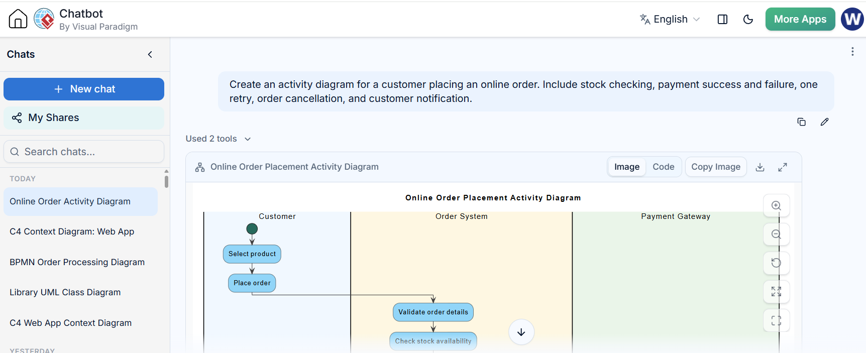
In modern software architecture, the gap between a business requirement and a technical specification is often bridged by modeling tools. Visual Paradigm has integrated AI capabilities to transform this process, allowing teams to move rapidly from textual descriptions to structured system diagrams. This tutorial explores the architecture of an online order process, demonstrating how to leverage AI to draft complex workflows and then refine them using professional modeling standards.
The AI-Driven Modeling Workflow
The integration of AI into the Visual Paradigm ecosystem is designed to accelerate the “exploration phase” of system design. Instead of manually placing shapes and drawing connectors, the architect provides a natural language prompt. The AI interprets the business logic, identifies the necessary actors (such as the Customer and the Payment Gateway), and constructs the initial flow.
This approach shifts the role of the architect from a drafter to a reviewer. The AI generates a draft based on the provided scope, handling the syntax and layout, while the human expert ensures the logic aligns with the specific project context. The workflow typically follows these steps:
- Define the Scope: The user identifies the process boundaries (e.g., “Customer placing an online order”).
- Identify Components: Key participants are listed, such as the Order System, Stock, and Payment Gateway.
- Map the Flow: The AI constructs the sequence of activities, including decision points (diamonds) for success and failure paths.
- Refine and Import: The generated code (PlantUML) is reviewed for accuracy and imported into the Visual Paradigm environment for editing.
Deconstructing the Online Order Architecture
To understand the complexity handled by the AI, we must look at the specific logic embedded in the online order scenario. The process is not linear; it involves branching paths for inventory management and financial transactions.
1. The Customer and Order Initiation
The workflow begins with the Customer acting as the primary actor. The process initiates when a product is selected and an order is placed. In modeling terms, this is the entry point of the activity diagram. The diagram must clearly distinguish between the customer’s actions and the system’s response.
2. Inventory Management and Validation
Once the order is placed, the Order System takes over. A critical step is validating the order details and checking stock availability. The diagram must account for two distinct outcomes:
- Success Path: If the item is in stock, the system reserves the inventory.
- Failure Path: If the item is out of stock, the system must suggest alternatives or cancel the order, followed by notifying the customer.
3. The Payment Gateway Loop
The most complex part of this architecture is the payment process. Financial transactions require robust error handling. The diagram illustrates a “retry” mechanism:
- The system attempts to process the payment via the Payment Gateway.
- If successful, the order is confirmed.
- If failed, the system requests a retry. The customer re-enters details, and the payment is attempted again.
- If the second attempt also fails, the order is cancelled, inventory is released, and the customer is notified.
Translating Logic to Diagram Code
When the AI generates the diagram, it produces code that defines the visual structure. In this ecosystem, the AI typically uses a syntax similar to PlantUML to define the swimlanes and activities. Below is an example of how the AI translates the business logic into code structure.
@startuml
title Online Order Placement Activity Diagram
skinparam swimlane {
  BackgroundColor White
  FontColor Black
  FontSize 14
}

skinparam activity {
  BackgroundColor #81D4FA
  MaximumWidth 150
}

|Customer|
start :Select product;
:Place order;

|Order System|
:Validate order details;
:Check stock availability;

if (Item in stock?) then (yes)
  :Reserve inventory;
else (no)
  :Suggest alternatives;
  :Cancelled order;
  :Notify customer;
  stop
endif

|Payment Gateway|
:Process payment;
if (Payment successful?) then (yes)
  :Confirm payment;
else (no)
  :Request retry;
endif

|Customer|
:Re-enter payment details;

|Payment Gateway|
:Process payment (retry);
if (Payment successful?) then (yes)
  :Confirm payment;
else (no)
  :Cancelled order;
  :Release reserved inventory;
  :Notify customer;
  stop
endif

|Order System|
:Create order record;
:Commit inventory;
:Generate order confirmation;

|Customer|
:Receive order confirmation notification;
stop
@enduml
Importing and Finalizing the Model
The power of this system lies in the “Import” functionality. Once the AI has generated the code and the user has reviewed it for missing cases (such as the specific retry logic mentioned above), the diagram is imported into Visual Paradigm Desktop. This converts the text-based code into a fully editable graphical model.
This allows the architect to:
- Adjust the layout for better readability.
- Refine the terminology to match the specific project glossary.
- Ensure all edge cases (failure paths) are visually represented.
Conclusion
The integration of AI into the Visual Paradigm workflow streamlines the creation of complex system architectures. By delegating the initial drafting to the AI and focusing the human effort on reviewing logic and refining the model, teams can produce high-quality diagrams in a fraction of the time. This hybrid approach ensures that the final model is not just visually correct, but logically sound and aligned with the project’s business requirements.

 English
 Arabic
 Chinese (Simplified)
 Dutch
 French
 German
 Italian
 Japanese
 Korean
 Portuguese
 Russian
 Spanish