


1. Introduction: Why BPMN + Visual Paradigm?
In today’s fast-paced business environment, clarity, consistency, and automation are critical for operational success. Business Process Model and Notation (BPMN) provides a universal language for visualizing workflows, while Visual Paradigm delivers the most intuitive, powerful, and enterprise-ready tool to bring those models to life.
This guide walks you through the end-to-end process of designing, validating, and optimizing a business process using BPMN 2.0.2 standards and Visual Paradigm’s advanced features—from initial concept to executable workflow.
Whether you’re an HR professional, process analyst, manager, or developer, this guide equips you with the tools to model, simulate, and improve real-world processes with confidence.
✅ Why Visual Paradigm?
Full BPMN 2.0.2 compliance
Drag-and-drop interface with auto-routing
Built-in validation and error detection
Process simulation & performance analytics
RACI/CRUD matrix generation
Team collaboration & cloud sync
2. Core Concept: The “Swimlane” Architecture in BPMN
BPMN uses a visual metaphor inspired by swimming pools to organize responsibilities and improve readability.
🏊♂️ Swimlanes: Who Does What?
| Element | Purpose | Example |
|---|---|---|
| Pool | Represents a major participant or organization. | ABC Company, Online Shop, Customer |
| Blackbox Pool | A pool with no internal details—used for external entities (e.g., Customer). | Customer pool (external, no internal tasks shown) |
| Lane | Subdivision within a pool to represent roles, departments, or systems. | Employee, Manager, HR, Warehouse, Payment Gateway |
🎯 Best Practice:
Use one pool per organization.
Use lanes to reflect real roles, not organizational charts.
Avoid over-nesting lanes—keep it simple and aligned with process flow.
3. BPMN Notation Guide: Symbols, Roles & Logic
BPMN’s visual language is both intuitive and precise. Master these elements to create professional, executable diagrams.
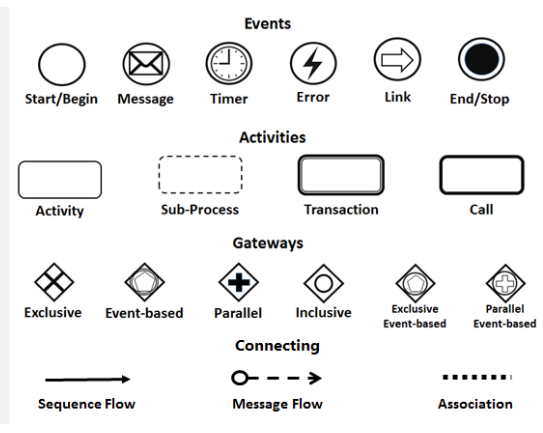
🔹 Events (Circles)
Represent occurrences that trigger or conclude a process.
| Type | Symbol | Use Case |
|---|---|---|
| Start Event | Thin-bordered circle | “Leave Application Submitted” |
| Message Start Event | Message icon inside circle | “Purchase Order Received” |
| End Event | Thick-bordered circle (often red) | “Leave Taken” or “Order Delivered” |
💡 Use message start events for external triggers (e.g., API calls, emails).
🔹 Activities (Rounded Rectangles)
Represent work units performed by individuals or systems.
| Type | Symbol | Description |
|---|---|---|
| Task/Activity | Rounded rectangle | Atomic action: e.g., “Evaluate Application” |
| Sub-Process | Rounded rectangle with dotted border or + sign | Complex task with internal steps (e.g., “Process Payment”) |
📌 Expand sub-processes into child diagrams for deeper analysis.
🔹 Gateways (Diamonds)
Control the flow logic of the process.
| Type | Symbol | Behavior |
|---|---|---|
| Exclusive (XOR) | Diamond with X | Only one path is taken (e.g., “Approved? Yes/No”) |
| Parallel (+) | Diamond with + | All outgoing paths execute simultaneously |
| Inclusive (OR) | Diamond with OR | One or more paths may execute |
| Event-Based | Diamond with event icon | Waits for an external event (e.g., “Payment Received”) |
⚠️ Use exclusive gateways for decisions, parallel for concurrent tasks.
🔹 Connecting Objects (Lines & Arrows)
Define how elements are linked.
| Object | Symbol | Use Case |
|---|---|---|
| Sequence Flow | Solid line with arrow | Internal flow within a pool (e.g., Employee → Manager) |
| Message Flow | Dashed line with arrow | Inter-pool communication (e.g., Manager → HR) |
| Association | Dotted line | Links data, annotations, or artifacts to elements |
✅ Rule of Thumb:
Sequence Flow = Inside the pool (same participant)
Message Flow = Between pools (different participants)
Never mix them—it breaks BPMN semantics.
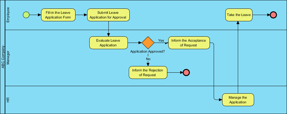
4. Case Study: ABC Company Leave Application Process
This real-world example demonstrates how BPMN clarifies cross-functional workflows.
🔄 Process Flow Summary
| Step | Actor | Action |
|---|---|---|
| 1 | Employee | Submits leave application |
| 2 | Manager | Evaluates request |
| 3 | Exclusive Gateway | “Approved?” → Yes → HR; No → End |
| 4 | HR | Manages application (update records) |
| 5 | Employee | Takes leave → End Event |
📌 This is a classic example of a private, internal process with clear ownership and a defined end state.
5. Step-by-Step: Building the Leave Process in Visual Paradigm
Follow this professional workflow to create a fully compliant and interactive BPMN diagram.
✅ Step 1: Launch Visual Paradigm
-
Open Visual Paradigm Desktop or VP Online.
-
Sign in (free 30-day trial available at https://www.visual-paradigm.com/download/).
✅ Step 2: Create a New BPMN Diagram
-
Go to Diagram > New.
-
Select Business Process Diagram (BPD).
-
Name it:
Leave_Application_Process.
✅ Step 3: Set Up Pools and Lanes
-
Drag a Pool from the toolbar → Name it:
ABC Company. -
Right-click the pool → Add Lane → Add:
-
Employee -
Manager -
HR
-
-
For the Customer, create a Blackbox Pool (external entity) and label it
Customer.
🎯 Use blackbox pools for external participants whose internal processes are irrelevant.
✅ Step 4: Add the Start Event
-
Drag a Start Event from the palette.
-
Drop it in the Employee lane.
-
Double-click to rename:
Leave Application Submitted.
✅ Step 5: Add the First Activity
-
Drag a Task (rounded rectangle) and connect it to the Start Event using Sequence Flow.
-
Label it:
Fill in Leave Application Form.
✅ Step 6: Add the Manager’s Task
-
Drag another Task into the Manager lane.
-
Connect it via Sequence Flow.
-
Label:
Evaluate Leave Application.
✅ Step 7: Insert the Exclusive Gateway
-
Drag an Exclusive Gateway (XOR) into the Manager lane.
-
Connect the “Evaluate” task to the gateway.
-
From the gateway, draw two Sequence Flows:
-
One labeled “Yes” → to HR
-
One labeled “No” → to End Event
-
📌 Label all outgoing flows from gateways clearly (Yes/No, Approved/Rejected).
✅ Step 8: Add HR Task and End Event
-
Drag a Task into the HR lane → Label:
Manage the Application. -
Connect it from the “Yes” flow.
-
Drag an End Event (red circle) into the Employee lane.
-
Connect it from the HR task → Label:
Take the Leave.
✅ Step 9: Add Message Flows (Optional)
-
Use Message Flow (dashed arrow) from Manager to HR to show communication.
-
Use Message Flow from HR back to Employee to notify of approval.
✅ Step 10: Validate & Refine
-
Click Tools > Validate Diagram.
-
Fix any errors (e.g., missing end events, invalid flow).
-
Use Auto-Layout to clean up the diagram.
✅ Step 11: Simulate & Analyze
-
Go to Tools > Process Simulation.
-
Assign:
-
Resources: e.g., “Manager (1)”, “HR (1)”
-
Time: e.g., “Evaluate” = 1 day, “Manage” = 2 hours
-
Costs: e.g., $5 per approval
-
-
Run simulation → View:
-
Process duration
-
Resource utilization
-
Bottleneck analysis
-
✅ Step 12: Export & Share
-
Export to:
-
PDF (for documentation)
-
HTML (for web sharing)
-
PNG/SVG (for presentations)
-
-
Generate:
-
RACI Matrix (auto-generated from lanes)
-
CRUD Matrix
-
Process Specification Document
-
📤 Share via VP Online or team workspace for collaborative review.
6. Pro Tips & Best Practices for Effective Modeling
| Tip | Why It Matters |
|---|---|
| Use Verb + Noun Format | E.g., “Submit Form”, “Approve Request” → Clear and consistent |
| Always Label Flows | Avoid ambiguity: label “Yes”, “No”, “Approved”, “Rejected” |
| Model Left to Right | Improves readability and alignment with BPMN standards |
| Use Sub-Processes for Complexity | Hide internal steps (e.g., “Verify Leave Balance”) to keep main diagram clean |
| Avoid Crossing Sequence Flows | Use message flows for inter-pool communication |
| Validate Before Sharing | Ensure compliance with BPMN 2.0.2 |
| Simulate Early and Often | Uncover inefficiencies before implementation |
✅ Pro Insight:
“A well-labeled, validated diagram is not just a picture—it’s a living document that drives decisions.”
7. Beyond Leave Requests: Applying BPMN to Other Processes
The same principles apply to other critical workflows. Here’s how to adapt BPMN with Visual Paradigm:
| Process | BPMN Application |
|---|---|
| Online Shopping Checkout | Model: Cart → Payment → Order Confirmation → Delivery |
| Procurement Request | Show: Request → Approval → Vendor Selection → PO → Invoice |
| Customer Support Ticketing | Map: Ticket Created → Assigned → Resolved → Closed |
| Onboarding New Hires | Visualize: HR → IT → Department → Training |
🛠️ Use Visual Paradigm’s template library to start quickly with pre-built process models.
8. Conclusion & Next Steps
The ABC Company Leave Application Process demonstrates how BPMN transforms complex, cross-functional workflows into clear, executable, and analyzable diagrams.
With Visual Paradigm, you gain the ability to:
-
Design professional BPMN diagrams with ease,
-
Validate for compliance,
-
Simulate performance,
-
Generate reports and matrices,
-
Collaborate in real time.
✅ Your Next Move:
Download Visual Paradigm (free 30-day trial): https://www.visual-paradigm.com/download/
Follow the step-by-step guide above to recreate the leave process.
Apply BPMN to your own process—start with a simple workflow like customer onboarding or purchase approval.
Explore tutorials: https://www.visual-paradigm.com/tutorials/
📌 Final Thought:
“If you can’t model it, you can’t improve it.”
With BPMN and Visual Paradigm, you’re not just drawing diagrams—you’re building the foundation for process excellence, automation, and digital transformation.
BPMN Articles
- What is BPMN? – Visual Paradigm Guide: An introductory guide explaining the purpose, structure, and benefits of BPMN in business process design.
- BPMN Notation Overview – Visual Paradigm Guide: A comprehensive overview of BPMN notation elements, including events, activities, gateways, and artifacts used in process modeling.
- How to Draw a BPMN Diagram – Visual Paradigm Tutorial: A step-by-step tutorial on creating professional BPMN diagrams using an intuitive interface and industry best practices.
- Understanding Pools and Lanes in BPMN – Visual Paradigm User Guide: A detailed explanation of how to use pools and lanes to represent different departments, organizations, or roles within a process.
- As-Is to To-Be Business Process Modeling Tutorial: A guide on analyzing current business processes (As-Is) and designing improved future processes (To-Be) using BPMN tools.
- How to Create a BPMN Conversation Diagram in Visual Paradigm: A comprehensive guide for modeling interactions between business partners using specialized conversation diagrams.
- How to Generate a RACI Chart from BPMN Models: Instructions on how to automatically generate a RACI matrix from existing BPMN diagrams to clarify roles and responsibilities.
- How to Animate Business Processes with Visual Paradigm: A tutorial on creating dynamic, animated business process diagrams to enhance visualization and team communication.
- Unlocking Efficiency: Performing Gap Analysis with BPMN: An article explaining how BPMN can be leveraged to visualize and analyze shortfalls in business processes for optimization.
- AI Business Process Improvement Tool – Visual Paradigm Product Updates: An announcement regarding a tool that uses AI to transition from a problem statement directly to diagrams, KPIs, and analysis.
