


Unified Modeling Language (UML) is a standardized modeling language consisting of an integrated set of diagrams, developed to help system and software developers for specifying, visualizing, constructing, and documenting the artifacts of software systems, as well as for business modeling and other non-software systems.
What is UML?
The UML represents a collection of best engineering practices that have proven successful in the modeling of large and complex systems. The UML is a very important part of developing object oriented software and the software development process. The UML uses mostly graphical notations to express the design of software projects. Using the UML helps project teams communicate, explore potential designs, and validate the architectural design of the software.
Key Characteristics:
-
Standardized notation recognized globally by OMG (Object Management Group)
-
Language-independent – works with any programming language
-
Multi-view approach – different diagrams for different stakeholders
-
Visual-first – graphical representations enhance understanding
-
Extensible – supports customization through profiles and stereotypes
The Origin & History of UML
The “Three Amigos” Unified Method
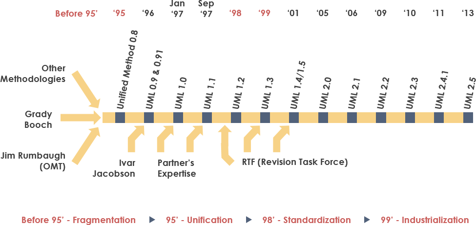
UML resulted from the unification of three pioneering object-oriented methodologies:
-
Object Modeling Technique (OMT) – James Rumbaugh, 1991
-
Best for analysis and data-intensive information systems
-
-
Booch Method – Grady Booch, 1994
-
Excellent for design and implementation; strong Ada language foundation
-
-
OOSE (Object-Oriented Software Engineering) – Ivar Jacobson, 1992
-
Introduced Use Cases for understanding system behavior
-
Timeline of UML Evolution:
-
1994: Rumbaugh joins Booch at Rational Corp → “Unified Method” begins
-
1995: Jacobson joins; Use Cases integrated → “Unified Modeling Language” born
-
1996: OMG issues first RFP; UML Partners consortium forms
-
1997: UML 1.0 submitted to OMG; UML 1.1 adopted fall 1997
-
1997-2006: Enhanced from 1.1 → 1.5 → 2.0 → 2.1
-
Current: UML 2.5 (latest stable version)

Why UML Matters
As software systems grow in complexity and strategic value, organizations need techniques to:
-
✅ Automate software production
-
✅ Improve quality while reducing cost and time-to-market
-
✅ Manage architectural complexity (distribution, concurrency, security, fault tolerance)
-
✅ Solve recurring design problems with proven patterns
Primary Design Goals of UML:
-
Provide a ready-to-use, expressive visual modeling language
-
Offer extensibility mechanisms to extend core concepts
-
Remain independent of programming languages and processes
-
Establish a formal basis for understanding the modeling language
-
Encourage growth of the OO tools market
-
Support higher-level concepts: collaborations, frameworks, patterns, components
-
Integrate industry best practices
UML Diagram Types Overview
UML 2.x defines 13 diagram types organized into two categories:
🔷 Structure Diagrams (Static View)
Show the static structure of the system and relationships between elements:
| Diagram | Purpose |
|---|---|
| Class Diagram | Types of objects and static relationships |
| Component Diagram | Software components and dependencies |
| Deployment Diagram | Physical deployment of artifacts to hardware |
| Object Diagram | Snapshot of instances at a point in time |
| Package Diagram | Organization of model elements into packages |
| Composite Structure Diagram | Internal structure of classes/components |
| Profile Diagram | Domain-specific stereotypes and extensions |
🔶 Behavior Diagrams (Dynamic View)
Show dynamic behavior and changes over time:
| Diagram | Purpose |
|---|---|
| Use Case Diagram | Functional requirements and actor interactions |
| Activity Diagram | Workflows, business processes, and operations |
| State Machine Diagram | States, transitions, and event-driven behavior |
| Sequence Diagram | Time-ordered interactions between objects |
| Communication Diagram | Object collaborations (focus on links, not time) |
| Interaction Overview Diagram | High-level flow of control between interactions |
| Timing Diagram | Behavior of objects over specific time periods |
Structure Diagrams Deep Dive
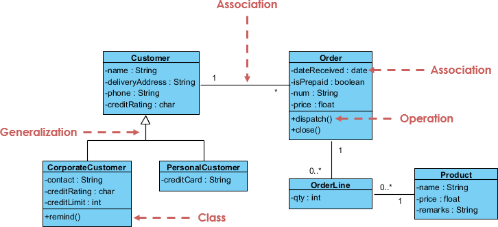
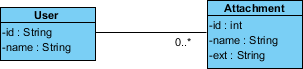
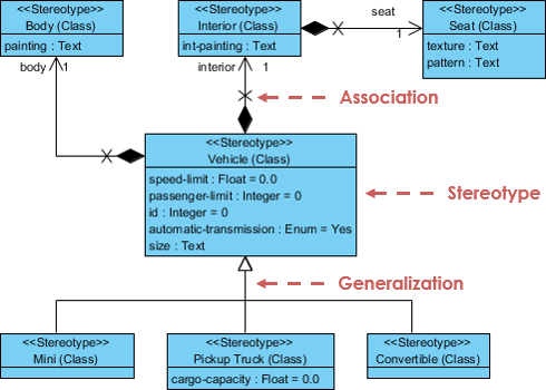
Class Diagram
The central modeling technique for object-oriented methods. Describes types of objects and static relationships.
Key Relationships:
-
Association: Relationships between instances (e.g., person works for company)
-
Inheritance: “Is-a” relationships corresponding to OO inheritance
-
Aggregation: “Has-a” composition relationships
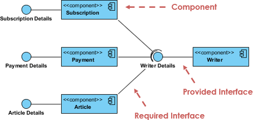
Component Diagram
Depicts how components are wired together to form larger software systems. Illustrates architectures and dependencies between run-time, executable, and source code components.
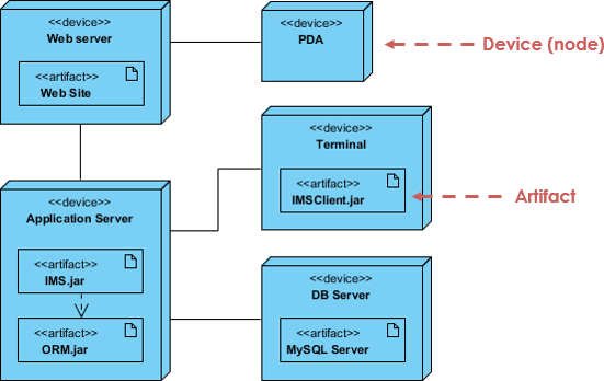
Deployment Diagram
Models the physical aspect of OO systems: architecture as deployment of software artifacts to hardware targets. Visualizes run-time configuration in a static view.
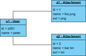
Object Diagram
A graph of instances showing a snapshot of system state at a point in time. Unlike abstract class diagrams, object diagrams are concrete and show actual data values.
Class Diagram vs Object Diagram Example:
Class Diagram (abstract model):
Object Diagram (concrete instance – Peter uploading two attachments):
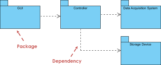
Package Diagram
Shows packages and dependencies between them. Ideal for modeling multi-layered applications and organizing large-scale projects.
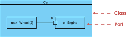
Composite Structure Diagram
Added in UML 2.0. Shows internal structure of a class and collaborations at a micro point-of-view. Includes internal parts, ports, and connectors.
Profile Diagram
Enables creation of domain and platform-specific stereotypes. Define relationships between stereotypes using composition or generalization, and visualize tagged values.
Behavior Diagrams Deep Dive
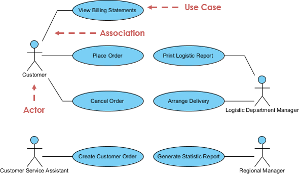
Use Case Diagram
Describes functional requirements in terms of use cases and actors. Think of it as a “menu” showing what the system offers to its users.
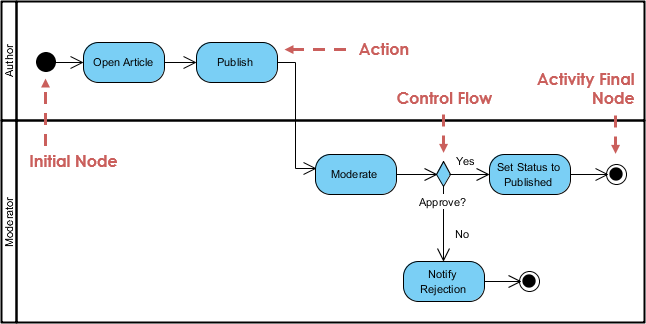
Activity Diagram
Graphical representation of workflows with support for choice, iteration, and concurrency. Models both computational and organizational processes.
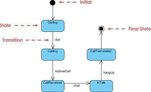
State Machine Diagram
Describes behavior based on states, transitions, and events. Based on David Harel’s state diagrams, it visualizes the entire lifecycle of objects.
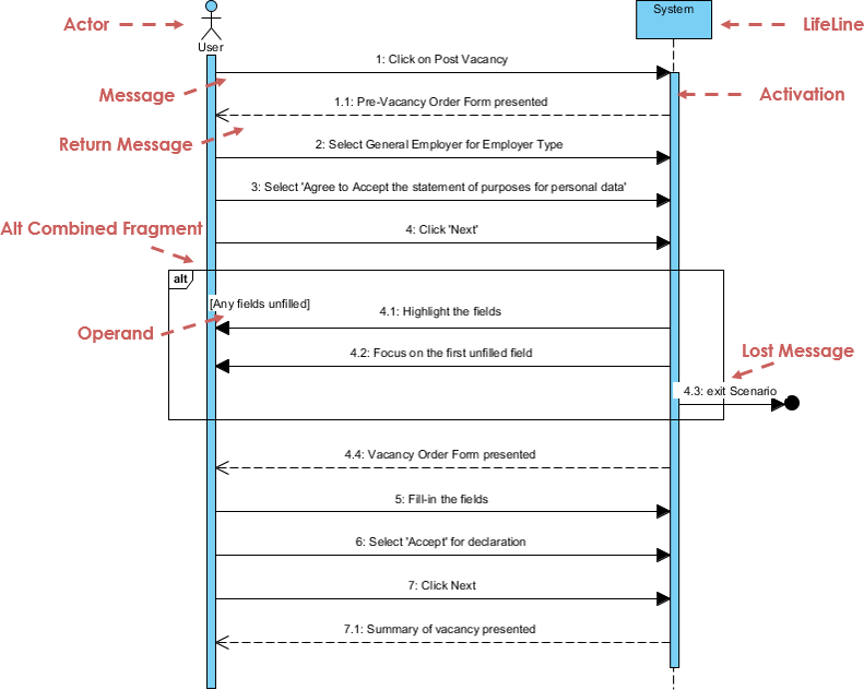
Sequence Diagram
Models collaboration of objects based on time sequence. Shows how objects interact in a particular scenario through message passing.
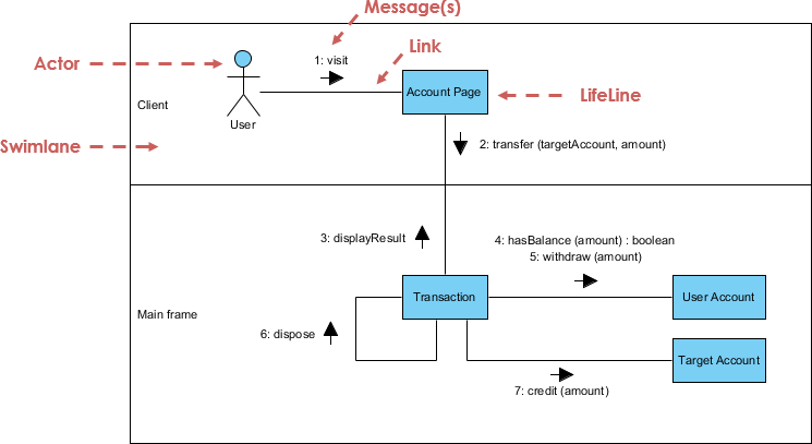
Communication Diagram
Similar to sequence diagrams but focused on object collaboration rather than time sequence. Semantically equivalent; many tools allow conversion between the two.
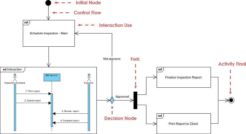
Interaction Overview Diagram
A variant of Activity Diagram where nodes represent interactions. Focuses on high-level flow of control with messages and lifelines hidden for clarity.
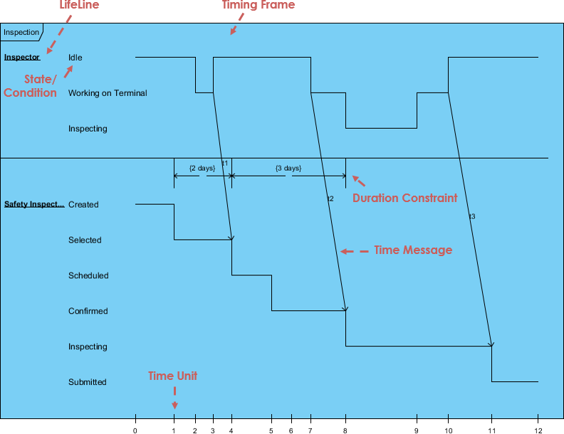
Timing Diagram
Shows behavior of objects over a given time period. A special form of sequence diagram with reversed axes: time increases left-to-right, lifelines arranged vertically.
🤖 AI-Powered UML Modeling: The Next Evolution
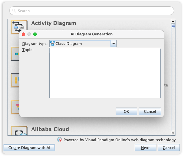
While UML provides the standard notation for system design, the way we build these models is transforming. Visual Paradigm has integrated cutting-edge AI Diagram Generation to help you move from concept to complex architecture in seconds.
What is AI-Powered UML?
AI-Powered UML combines natural language processing, machine learning, and model-driven engineering to automate the creation, refinement, and analysis of UML diagrams. Instead of manually drawing each element, you describe your system requirements in plain English, and AI generates standards-compliant diagrams instantly.
Key AI Features in Visual Paradigm
🔹 AI Diagram Chatbot
-
Plain English Input: Describe your system like “An e-commerce system where customers can browse products, add to cart, and checkout with payment processing”
-
Instant Generation: Watch Use Case, Class, Sequence, or Activity diagrams generate in seconds
-
Conversational Refinement: Ask follow-ups like “Add a Wishlist feature” or “Show error handling for payment failures”
-
Multi-Diagram Support: Generate 13+ UML diagram types from a single prompt
🔹 Desktop AI Generator
Access powerful UML generation capabilities directly within Visual Paradigm Desktop:
-
Professional-grade modeling with AI assistance
-
Seamless integration with code engineering (forward/reverse engineering)
-
Team collaboration and version control support
🔹 OpenDocs Knowledge Management
Embed AI-generated diagrams directly into documentation:
-
Keep technical knowledge base and visual models synchronized
-
Auto-update diagrams when requirements change
-
Generate project proposals and documentation from models
🔹 Intelligent Analysis & Critique
-
Quality Checks: AI identifies inconsistent multiplicities, missing relationships, or design anti-patterns
-
“Ask Your Diagram”: Query your model as a knowledge base: “What are the main use cases?” or “Summarize the payment flow”
-
Recommendations: Get suggestions for improving architecture, adding missing components, or optimizing interactions
Benefits of AI-Powered UML
| Benefit | Traditional UML | AI-Powered UML |
|---|---|---|
| Speed | Hours/days to draft initial diagrams | Seconds to generate first draft |
| Learning Curve | Steep; requires UML syntax mastery | Gentle; start with natural language |
| Consistency | Manual errors in notation/relationships | AI enforces UML standards automatically |
| Iteration | Redrawing required for changes | Conversational updates: “Add X”, “Remove Y” |
| Stakeholder Alignment | Diagrams may be too technical for non-devs | Generate simplified views for business users |
| Documentation Sync | Manual effort to keep docs/diagrams aligned | Auto-embed diagrams in living documentation |
| Design Quality | Relies on individual expertise | AI suggests patterns, flags anti-patterns |
| Accessibility | Requires specialized training | Lowers barrier for analysts, PMs, students |
Real-World Impact:
-
🚀 Accelerate Discovery: Validate architectural concepts before coding begins
-
🎯 Improve Communication: Bridge gap between business stakeholders and developers
-
🔍 Reduce Rework: Catch design flaws early through AI critique
-
📈 Scale Modeling: Manage complexity in large systems with AI-assisted organization
-
🔄 Enable Agility: Rapidly iterate designs in response to changing requirements
Traditional vs AI-Powered UML: Comparison
Workflow Comparison
Traditional UML Workflow:
Requirements → Manual Diagram Drafting → Peer Review → Revisions → Documentation → Implementation
          ↑_____________________________↓
               (Iterative, time-intensive)
AI-Powered UML Workflow:
Natural Language Prompt → AI Diagram Generation → Conversational Refinement → AI Quality Check → Auto-Documentation → Implementation
                              ↑_________________________↓
                                   (Rapid, collaborative iteration)
Capability Matrix
| Capability | Traditional Tools | AI-Enhanced Tools |
|---|---|---|
| Diagram Creation | Manual drag-and-drop | Text-to-diagram generation |
| Requirement Traceability | Manual linking | Auto-extraction from prompts |
| Multi-Diagram Consistency | Manual synchronization | AI-enforced coherence |
| Stakeholder Views | Create separate diagrams manually | Auto-generate simplified/technical views |
| Learning Support | Documentation/tutorials | Interactive AI guidance |
| Design Critique | Peer review only | AI-powered analysis + suggestions |
| Documentation | Manual export/copy | Auto-sync diagrams ↔ docs |
When to Use Which Approach
✅ Traditional UML is still valuable when:
-
You need pixel-perfect control over diagram layout
-
Working with legacy systems requiring precise reverse engineering
-
Teaching UML fundamentals (learning the notation manually builds deeper understanding)
-
Regulatory environments requiring manual audit trails
✅ AI-Powered UML excels when:
-
Rapid prototyping and exploration of design alternatives
-
Collaborating with non-technical stakeholders
-
Managing large, complex systems with many interrelated components
-
Accelerating onboarding of new team members
-
Maintaining living documentation that evolves with the system
💡 Best Practice: Use AI for initial exploration and iteration, then refine manually for final deliverables. Combine the speed of AI with the precision of human expertise.
Getting Started with Visual Paradigm
Free Tier: Community Edition
-
✅ All 13 UML diagram types supported
-
✅ Award-winning, intuitive interface
-
✅ Completely free for learning and non-commercial use
-
✅ AI Diagram Chatbot accessible via web
Professional Features (Paid)
-
🔹 Full desktop AI Generator integration
-
🔹 Code engineering (Java, C++, PHP, Python, etc.)
-
🔹 Team collaboration and version control
-
🔹 Advanced model validation and reporting
-
🔹 OpenDocs knowledge management integration
Quick Start Guide: AI-Powered Class Diagram
-
Go to chat.visual-paradigm.com
-
Type a prompt:
“Create a class diagram for a library management system with Book, Member, Librarian, and Loan classes. Include attributes and relationships.” -
Review the generated diagram
-
Refine conversationally:
“Add an ISBN attribute to Book”
“Show that a Member can have multiple Loans”
“Add a fine calculation method to Loan” -
Export or integrate: Download as image/PDF, or import into Desktop edition for code generation
🔗 Complete AI Diagram Generation Guide
- References
- Visual Paradigm Official Platform: Comprehensive UML modeling platform with AI-powered diagram generation, supporting all 13 UML diagram types, code engineering, and team collaboration features.
- Comprehensive Review: Visual Paradigm’s AI Diagram Generation Features: Independent analysis of Visual Paradigm’s AI capabilities, including text-to-diagram generation, conversational refinement, and integration workflows.
- UML Tool Features Overview: Detailed breakdown of Visual Paradigm’s UML modeling capabilities, including structural/behavioral diagrams, code engineering, and architectural pattern support.
- AI Diagram Generation Features: Official documentation of AI-powered UML generation, covering supported diagram types, prompt engineering tips, and desktop integration.
- Generate UML Class Diagrams with AI: Step-by-step tutorial for using AI to create class diagrams from natural language requirements, with examples and best practices.
- Visual Paradigm Desktop vs VP Online: Comprehensive Guide: Comparative analysis of deployment options, feature parity, and use-case recommendations for Visual Paradigm editions.
- AI-Assisted UML Class Diagram Generator: Dedicated feature page for AI-powered class diagram creation, including prompt examples and refinement workflows.
- UML Guides Category: Collection of Visual Paradigm’s official UML tutorials, diagram references, and modeling best practices.
- Miro AI UML Diagram Tool: Alternative AI-powered diagramming solution for UML, useful for collaborative whiteboarding and early-stage design exploration.
- AI Component Diagram Generation: Interactive example of generating component diagrams via AI chatbot, demonstrating prompt-to-diagram workflow.
- AI Chatbot Features: Overview of Visual Paradigm’s conversational AI assistant for diagram generation, refinement, and analysis.
- Guide to AI-Powered UML Diagram Generation: Official walkthrough of using Visual Paradigm’s AI tools for efficient UML modeling, including advanced prompting techniques.
- YouTube: AI-Powered UML Tutorial: Video demonstration of generating and refining UML diagrams using Visual Paradigm’s AI features.
-
💡 Pro Tip: Start with the free Community Edition and AI Chatbot to explore UML fundamentals. As your projects grow, leverage desktop AI integration for professional-grade modeling, code generation, and team collaboration.

- Ready to transform your modeling workflow?
Download Visual Paradigm Community Edition (Free) | Explore AI Diagram Generation
