


Introduction: Your Ultimate System Design Toolkit
Imagine having a universal language that bridges the gap between complex software architecture and clear visual communication. That’s exactly what Unified Modeling Language (UML) delivers. As the industry-standard modeling language managed by the Object Management Group (OMG), UML has become the go-to solution for software developers, system architects, and business analysts worldwide.
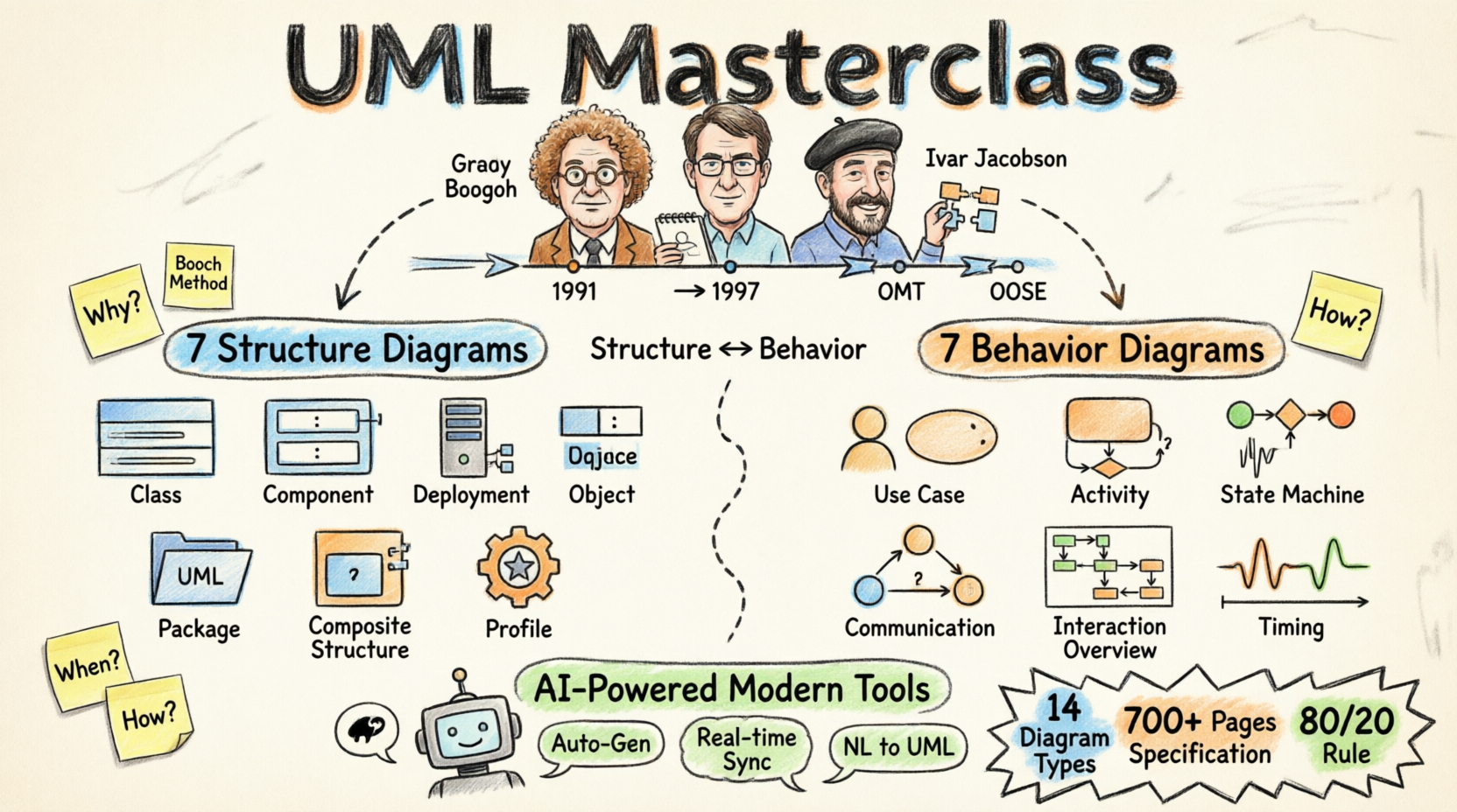
Think of UML as your Swiss Army knife for software development—it provides 14 specialized diagram types, each designed to tackle different aspects of system design, from static structures to dynamic behaviors. Whether you’re mapping out database relationships, visualizing user interactions, or planning system deployments, UML offers the precise tool you need.
In this comprehensive guide, we’ll explore UML’s powerful features, walk through each diagram type with real-world examples, and show you how modern AI-powered tools are making UML more accessible than ever. Let’s dive into what makes UML an indispensable asset for modern software development.
Product Overview: What is UML?
Unified Modeling Language (UML) is a standardized general-purpose modeling language that provides a comprehensive set of graphic notation techniques to create visual models for software-intensive systems.
Core Specifications:
-
Standard: Managed by Object Management Group (OMG)
-
Current Version: UML 2.5
-
Documentation: 700+ pages of specifications
-
Diagram Types: 14 distinct diagram categories
-
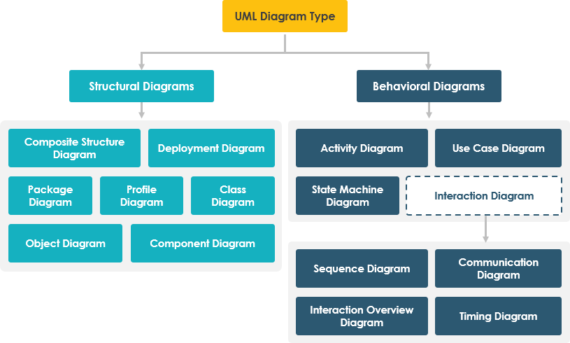
Categories: 7 Structure Diagrams + 7 Behavior Diagrams
Feature Set: The 14 UML Diagram Types
📐 STRUCTURE DIAGRAMS (Static Views)
Structure diagrams reveal the static architecture of your system, showing how components relate at different abstraction levels.
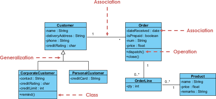
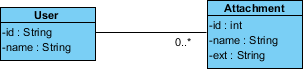
1. Class Diagram ⭐ Most Essential
Purpose: The backbone of object-oriented modeling, showing system classes, their attributes, operations, and relationships.
Key Relationships:
-
Association: Connections between instances (e.g., person works for company)
-
Inheritance: Subclass-superclass hierarchies
-
Aggregation: Part-whole compositions
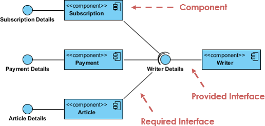
2. Component Diagram
Purpose: Visualizes how software components wire together to form larger systems, illustrating architectures and dependencies.
Use Cases:
-
Run-time components
-
Executable components
-
Source code components
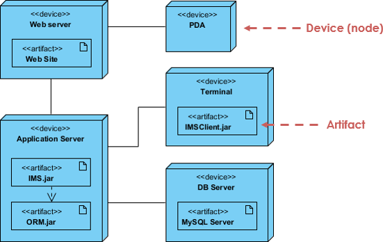
3. Deployment Diagram
Purpose: Models the physical architecture, showing software artifact distribution across hardware nodes.
Features:
-
Hardware configuration modeling
-
Software deployment mapping
-
Run-time configuration visualization
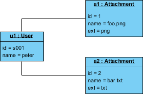
4. Object Diagram
Purpose: Captures a snapshot of system state at a specific moment, showing actual object instances and their data values.
Class vs Object Diagram:
-
Class Diagram: Abstract model (blueprint)
-
Object Diagram: Concrete instance (snapshot)
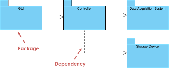
5. Package Diagram
Purpose: Organizes system elements into logical groups, showing dependencies between packages.
Ideal For:
-
Multi-layered applications
-
System modularization
-
Dependency management
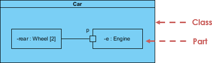
6. Composite Structure Diagram
Purpose: Reveals internal class structures and collaborations at a micro level.
Components:
-
Internal parts
-
Interaction ports
-
Connectors between parts
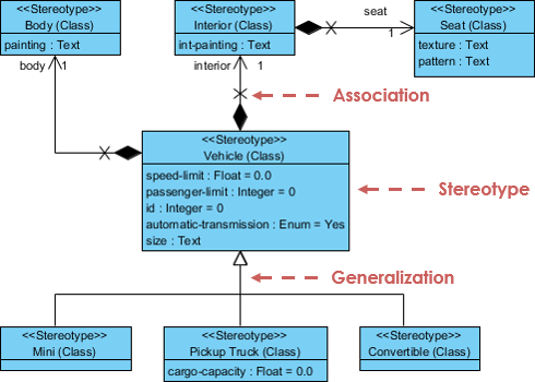
7. Profile Diagram
Purpose: Creates domain-specific stereotypes and custom extensions to standard UML.
Capabilities:
-
Custom stereotype creation
-
Tagged value definitions
-
Domain-specific modeling
⚡ BEHAVIOR DIAGRAMS (Dynamic Views)
Behavior diagrams capture the dynamic aspects of your system—how objects interact and change over time.
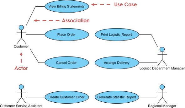
8. Use Case Diagram 🎯 Most Popular
Purpose: Models system functionality from the user’s perspective, showing actors and their interactions with use cases.
Benefits:
-
Requirements gathering
-
System scope definition
-
User-centric design
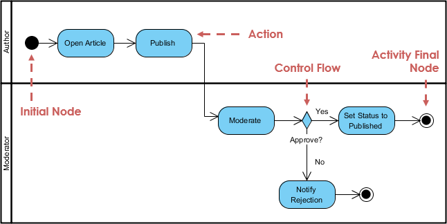
9. Activity Diagram
Purpose: Flowchart-style representation of workflows, supporting choices, iterations, and concurrent processes.
Applications:
-
Business process modeling
-
Algorithm visualization
-
Complex workflow mapping
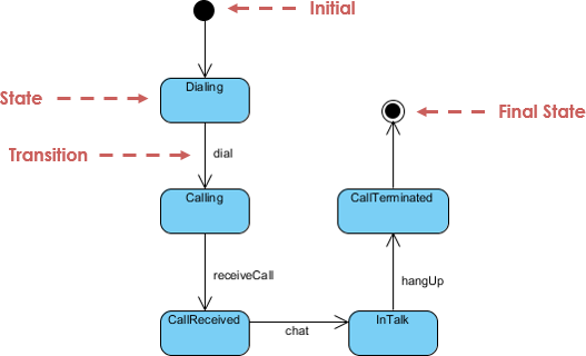
10. State Machine Diagram
Purpose: Illustrates object lifecycle, showing permitted states, transitions, and triggering events.
Use For:
-
State-based systems
-
Object lifecycle management
-
Event-driven architectures
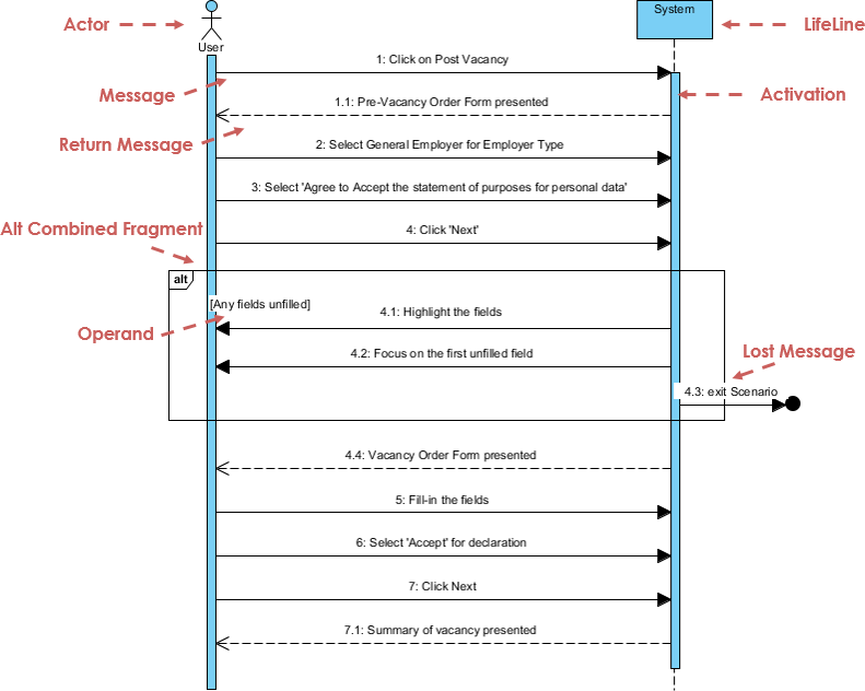
11. Sequence Diagram
Purpose: Models object collaborations over time, emphasizing message flow and temporal ordering.
Features:
-
Time-based interactions
-
Message sequencing
-
Use case scenario visualization
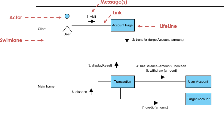
12. Communication Diagram
Purpose: Focuses on object collaborations and structural relationships rather than time sequence.
Note: Semantically equivalent to Sequence Diagrams—many tools allow conversion between them.
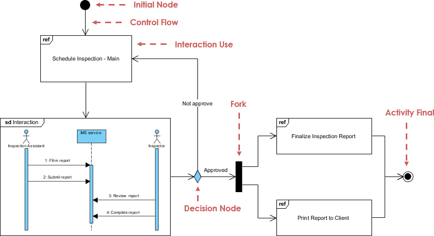
13. Interaction Overview Diagram
Purpose: High-level view of interaction flows, combining Activity Diagram structure with interaction nodes.
Advantage: Links detailed diagrams for high navigability
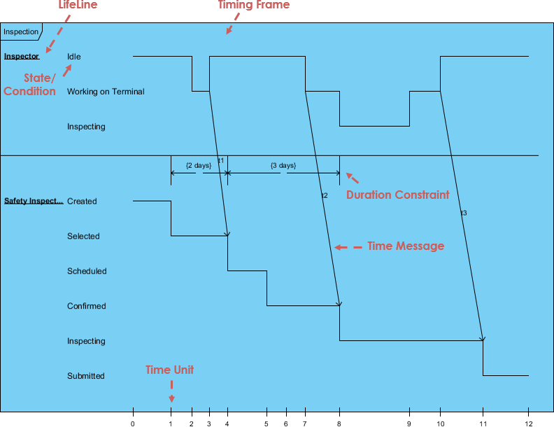
14. Timing Diagram
Purpose: Shows object behavior changes over specific time periods with reversed axes (time flows left to right).
Special Feature: Lifelines in separate vertical compartments
Popularity Analysis: Which Diagrams Matter Most?
According to UML usage surveys, diagram popularity breaks down as follows:
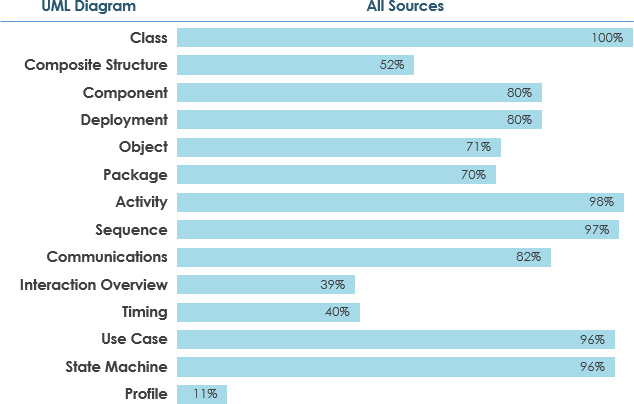
Usage Thresholds:
-
Widely Used: ≥ 60% adoption
-
Moderately Used: 40-60% adoption
-
Scarcely Used: ≤ 40% adoption
Key Insight: Grady Booch (UML co-creator) states: “For 80% of all software, only 20% of UML is needed.”
Recommended Learning Priority:
-
Use Case Diagrams
-
Class Diagrams
-
Sequence Diagrams
-
Activity Diagrams
-
State Machine Diagrams
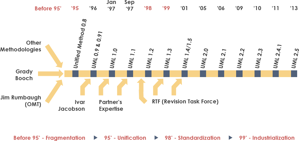
Historical Evolution: The Three Amigos Legacy
UML emerged from the unification of three pioneering object-oriented methods:
The Foundation (1991-1994)
-
OMT (Object Modeling Technique) – James Rumbaugh, 1991
-
Strength: Analysis and data-intensive systems
-
-
Booch Method – Grady Booch, 1994
-
Strength: Design and implementation
-
Background: Ada language expertise
-
-
OOSE (Object-Oriented Software Engineering) – Ivar Jacobson, 1992
-
Innovation: Use Cases for system behavior modeling
-
The Unification (1994-1997)
-
1994: Rumbaugh joins Booch at Rational Corp
-
1995: Jacobson joins, contributing Use Cases
-
1996: OMG issues Request for Proposal (RFP)
-
1997: UML 1.0 submitted; UML 1.1 adopted fall 1997
Major Contributors:
Digital Equipment Corp, HP, IBM, Microsoft, Oracle, Rational Software, TI, Unisys, and 10+ others
Version Timeline:
-
UML 1.0 → 1.1 → 1.5 → 2.0 → 2.1 → Current: 2.5
Why Choose UML? Key Benefits
1. Universal Communication Language
Bridges gaps between stakeholders:
-
Analysts ↔ Designers ↔ Developers ↔ Testers
-
Technical teams ↔ Business stakeholders
-
Documentation ↔ Implementation
2. Comprehensive Coverage
Addresses multiple system aspects:
-
Static Structure: Classes, components, deployments
-
Dynamic Behavior: Interactions, states, activities
-
Architecture: Distribution, concurrency, security
3. Industry Standards Integration
-
Language-independent
-
Process-independent
-
Formal semantic foundation
-
Extensible via stereotypes and profiles
4. Modern Development Support
-
Component-based development
-
Visual programming
-
Design patterns and frameworks
-
Model-driven architecture
5. Complexity Management
Tackles architectural challenges:
-
Physical distribution
-
Concurrency and replication
-
Load balancing and fault tolerance
-
Web-scale systems
Next-Gen Features: AI-Powered UML Modeling
Visual Paradigm has revolutionized UML creation with integrated AI capabilities:
🤖 AI Diagram Chatbot
Feature: Natural language to diagram conversion
How it works: Describe your system in plain English → Get instant UML diagrams
Access: chat.visual-paradigm.com
🌐 AI WebApps
Feature: Guided workflow creation
Benefits: Step-by-step AI assistance for complex diagrams
Access: ai.visual-paradigm.com
⚡ Desktop AI Generator
Feature: Professional-grade diagram generation
Integration: Direct access within Visual Paradigm Desktop
Guide: Diagram Generation Guide
📝 OpenDocs Knowledge Management
Feature: Integrated documentation hub
Capability: Sync AI-generated diagrams with technical docs
Access: OpenDocs Tool
Explore the complete AI ecosystem: AI Diagram Generation Guide
Getting Started: Your Learning Path
Recommended Tools
Visual Paradigm Community Edition
-
✅ Free for learning and personal use
-
✅ Supports all 14 UML diagram types
-
✅ Award-winning, intuitive interface
-
✅ International recognition
-
✅ Complete feature set for beginners
Download: Free Community Edition
Learning Strategy
Phase 1: Essentials (Weeks 1-2)
-
Use Case Diagrams
-
Class Diagrams
-
Basic relationships
Phase 2: Behavior Modeling (Weeks 3-4)
-
Sequence Diagrams
-
Activity Diagrams
-
State Machine Diagrams
Phase 3: Advanced Structures (Weeks 5-6)
-
Component Diagrams
-
Deployment Diagrams
-
Package Diagrams
Phase 4: Specialized Diagrams (Weeks 7-8)
-
Communication Diagrams
-
Interaction Overview
-
Timing Diagrams
-
Composite Structure & Profile Diagrams
Essential UML Terminology
Abstract Class: A class that cannot be instantiated directly
Actor: External entity that interacts with the system
Aggregation: “Has-a” relationship (hollow diamond notation)
Association: Connection between model elements
Attribute: Characteristic or property of a class
Class: Blueprint for creating objects
Component: Deployable code unit
Dependency: “Uses” relationship between classifiers
Generalization: Inheritance relationship (hollow arrow)
Interface: Contract defining behavior without implementation
Message: Communication between objects
Multiplicity: Quantity constraints (e.g., 0..*, 1..5)
Package: Logical grouping of UML elements
Polymorphism: Same interface, different implementations
Stereotype: Custom UML extension mechanism
Use Case: System action triggered by actor request
Recommended Reading List
Top UML Books:
-
UML Distilled – Martin Fowler
-
Quick reference guide
-
-
The Unified Modeling Language User Guide – Booch, Rumbaugh, Jacobson
-
From the creators themselves
-
-
UML 2 and the Unified Process – Jim Arlow, Ila Neustadt
-
Practical OOAD approach
-
-
Learning UML 2.0 – Russ Miles, Kim Hamilton
-
Comprehensive introduction
-
-
Applying Use Case Driven Object Modeling with UML – Doug Rosenberg
-
E-commerce case study
-
-
Design Patterns: Elements of Reusable Object-Oriented Software – Gang of Four
-
Classic patterns reference
-
-
Fundamentals of Object-Oriented Design in UML – Meilir Page-Jones
-
Design principles focus
-
-
UML for Java Programmers – Robert C. Martin
-
Language-specific guide
-
Conclusion: Your Path to Modeling Mastery
Unified Modeling Language stands as the cornerstone of modern software architecture design. With its 14 specialized diagram types, UML provides the versatility to model any system—from simple applications to enterprise-scale distributed architectures.
The Bottom Line: While UML’s 700+ page specification might seem daunting, remember that you don’t need to master everything at once. Focus on the essential 20% (Use Case, Class, Sequence, and Activity diagrams) that serves 80% of development needs, then expand your toolkit as projects demand.
The Future is Now: With AI-powered tools like Visual Paradigm’s intelligent diagram generation, creating professional UML models has never been more accessible. What once took hours of manual work can now be accomplished in minutes through natural language descriptions.
Your Next Steps:
-
Download Visual Paradigm Community Edition (free)
-
Start with Use Case and Class Diagrams
-
Practice with real-world projects
-
Leverage AI tools to accelerate learning
-
Join the global community of UML practitioners
Whether you’re a student learning software engineering fundamentals, a developer transitioning to architecture roles, or a business analyst seeking better communication tools, UML provides the visual language to bring your ideas to life.
Ready to start modeling? The tools are free, the resources are abundant, and the skills will serve you throughout your career. Dive in and start diagramming today!
- References
- Object Management Group (OMG): The international standards consortium that manages UML as a de facto industry standard.
- UML Specification: Official UML specification documentation maintained by OMG.
- Object Modeling Technique OMT: James Rumbaugh’s 1991 methodology that was best for analysis and data-intensive information systems.
- James Rumbaugh: Co-creator of UML and developer of OMT, one of the “Three Amigos.”
- Grady Booch: Co-creator of UML, known for the Booch method which was excellent for design and implementation.
- Ivar Jacobson: Co-creator of UML and creator of OOSE, introduced Use Cases to the unified method.
- AI Diagram Chatbot: Natural language interface for instant UML diagram generation through conversational AI.
- AI WebApps: Step-by-step AI-guided workflows for creating and evolving complex diagrams.
- Diagram Generator Guide: High-speed automated diagramming tools within Visual Paradigm ecosystem.
- OpenDocs: Central knowledge hub for managing AI-generated diagrams and technical documentation.
- AI Diagram Generation Ecosystem: Complete guide to Visual Paradigm’s AI-powered modeling tools.
- Free UML Tool Download: Visual Paradigm Community Edition – free UML software supporting all diagram types.
- What is Class Diagram?: Detailed guide to class diagrams, relationships, and modeling techniques.
- What is Component Diagram?: Comprehensive resource on component architecture modeling.
- What is Deployment Diagram?: Guide to modeling physical system architecture and software distribution.
- What is Object Diagram?: Tutorial on capturing system snapshots and object instances.
- What is Package Diagram?: Resource on organizing system elements into logical groups.
- What is Composite Structure Diagram?: Guide to modeling internal class structures and collaborations.
- What is Profile Diagram?: Tutorial on creating domain-specific UML extensions and stereotypes.
- What is Use Case Diagram?: Comprehensive guide to modeling system functionality from user perspective.
- What is Activity Diagram?: Resource on workflow modeling with support for choice, iteration, and concurrency.
- What is State Machine Diagram?: Guide to modeling object lifecycles and state-based systems.
- What is Sequence Diagram?: Tutorial on time-based object collaboration and message sequencing.
- What is Communication Diagram?: Resource on object collaboration emphasizing structural relationships.
- What is Interaction Overview Diagram?: Guide to high-level interaction flow modeling.
- What is Timing Diagram?: Tutorial on modeling object behavior changes over specific time periods.
- Professional UML Design Tool: Visual Paradigm’s professional UML modeling features and capabilities.
Example Diagrams:
- Class Diagram Example
- Component Diagram Example
- Deployment Diagram Example
- Class vs Object Diagram Comparison
- Object Diagram Example
- Package Diagram Example
- Composite Structure Diagram Example
- Profile Diagram Example
- Use Case Diagram Example
- Activity Diagram Example
- State Machine Diagram Example
- Sequence Diagram Example
- Communication Diagram Example
- Interaction Overview Diagram Example
- Timing Diagram Example
