What is UML?
Unified Modeling Language is an open standard graphical notation for system development proposed Object Management Group. The notation is based on work from Booch, Rumbaugh, Jacobson . UML is a modeling language to express and design documents, software particularly useful for oriented oriented design. The language can be used from general initial design to very specific detailed design across the entire software development lifecycle. The definition of UML is defined as following:
- Unified Modeling Language ( UML ) is a graphical language for the modeling and developing of software systems. The UML diagrams become a common work product developers use to discuss all phases of software development from requirements analysis, design and implementation. The goal here is to model the software system before you build it.
- Quote: “The Unified Modeling Language (UML) is a family of graphical notations, backed by single meta-model, that help in describing and designing software systems, particularly software systems built using the object-oriented (OO) style.” [Martin Fowler – UML Distilled] pg 1.
Why UML?
As software architectures grow in size and complexity so does the need for software models. UML is the software industry’s dominant modeling language. It is currently a defacto standard adopted by the Object Management Group, the world’s largest software consortium. It is difficult to find a software project with with more than 10 developers who do not use UML in some way to specify their architecture.
Here is some more other facts for using of UML in our software development process:
- Software is getting increasingly more complex: an pretty old version of Windows XP > 40 million lines of code.
- A single programmer cannot manage this amount of code in its entirety.
- Code is not easily understandable by developers who did not write it.
- We need simpler representations for complex systems: w Modelling is a means for dealing with complexity.
What is a model?
- A model is an abstraction of the real thing, leaving out details.
- “The collection of all the elements that describe your system, including their connections to each other, make up your model.” (Russ and Hamilton 12).
when we use UML to create models of a system under developed before we code the software, they represent the problem in a simplified way. They provide a structure for problem solving. They help in understanding how one can proceed with the problem at hand. They also allow to experiment with multiple solutions. Since the models are created before the actual development of the system, we can understand different possibilities, problems, options etc. This also leads to decrease in the development costs. Since the time will not be wasted in trials and errors the product will be ready in lesser time. Models also help manage the complexity of the problem so the planning of the development, allocation of the resources like machines, programmers, testers can be done easily.
What UML is NOT?
- UML is not a notation, but it is a language.
- UML is not owned by anyone. It is open to be used by anyone who wishes to use it. It is not proprietary.
- UML is not process or a method.
- UML encourages the use of object-oriented techniques and iterative software development lifecycles.
- UML is not difficult. It is large, but one need not know it entirely. Also there is no need to use or understand every small thing in it.
- UML is not time consuming. If properly used, use of UML cuts down the development costs. At the same time it gives the advantage of easy understanding and communication, increased productivity and better quality.
- UML is not limited. It is flexible enough to allow newer vocabulary (concepts, words and terms), properties (additional information about the words) and semantics (language rules) which are required for a specific domain.
Objective of UML
- A visual modeling language and not a visual programming language. Although some modeling tools have code generators and some can reverse engineer models from code.
- It is intended to create diagrams that can support the software development process, however, UML is NOT a software development process or development method. Therefore UML is process independent.
- A standard language for creating software blueprints.
- A communication tool.
- A language for documenting requirements, architecture, tests, project planning, etc…
- It is intended for software systems but can model other systems.
- It is intended to support the object-oriented development process.
- It can capture both static structures and dynamic behavior of a system.
- UML diagrams can help stakeholders understand, discuss and agree on the requirements.
- UML diagrams can help abstract complicated processes to a level that is easier to understand.
- UML diagrams help facilitate problem solving.
What Does a Modeling Language Provide?
- Model Elements: Concepts and Semantics
- Notation: Visual Rendering of Model Elements
- Guidelines: Hints and Suggestions for Using Elements in Notation
Brief History
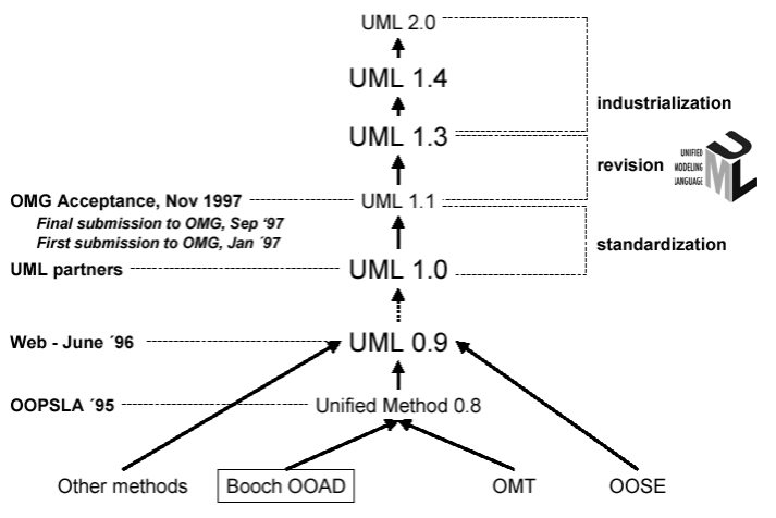
Back in the late 80s, when we started modeling, there were many different methodologies. And each methodology had its own notations. The problem was that if different people were using different notations, somewhere along the line somebody had to do a translation. A lot of times, one symbol meant one thing in one notation, and something totally different in another notation. In 1991, everybody started coming out with books. Grady Booch came out with his first edition. Ivar Jacobson came out with his, and Jim Rumbaugh came out with his OMT methodology. Each book had its strengths as well as its weaknesses. OMT was really strong in analysis, but weaker in design. The Booch methodology was stronger in design and weaker in analysis. And Ivar Jacobson’s Objectory was really good with user experience, which neither Booch nor OMT really took into consideration back then. Booch, Jacobson merged the two methods in 1994 and then Rumbaugh joined in 1995. UML 1.1 was published in 1997 from OMG includes the input from others, e.g. Yourden. The UML v2.x is the most current version.
Release Dates
- 1995 – UML 0.8
- 1996 – UML 0.9 – Three Amigos
- 1997 – OMG takes over.
- 1997 – OMG UML 1.1
- 1998 – OMG UML 1.2
- 1999 – OMG UML 1.3
- 2001 – OMG UML 1.4
- 2003 – OMG UML 1.5
- 2003 – OMG UML 2.0 – Adopted
- 2005 – OMG UML 2.0 – Final
- 2006 – OMG UML 2.1
- UML2.1.2 (11/04/07 ) – Current version as of 05/27/08
The motivation of the Method Unification by the “three Amegos”
- Fact that Individual Methods Evolving Towards Each Other Independently
- Unification of Semantics and Notation to Bring Stability to OO Design Marketplace
- Anticipation that Unification would Improve Earlier, Individual Methods
UML Partners
- Rational Software Corporation
- IBM
- Hewlett-Packard
- I-Logix
- ICON Computing
- Intellicorp
- MCI Systemhouse
- Microsoft
- ObjecTime
- Oracle
- Platinum Technology
- Taskon
- Texas Instruments/Sterling Software
- Unisys
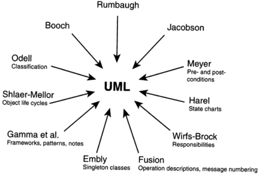
UML Notation Input for different Methods before the Unification
UML represents the unification of the Booch, OMT, and Objectory notations, as well as the best ideas from a number of other methodologists as shown in Figure below. By unifying the notations used by these object-oriented methods, the Unified Modeling Language provides the basis for a de facto standard in the domain of object-oriented analysis and design founded on a wide base of user experience.”
The Role of Notation
Notation plays an important part in any model ”it is the glue that holds the process together. “Notation has three roles:
- It serves as the language for communicating decisions that are not obvious or cannot be inferred from the code itself.
- It provides semantics that are rich enough to capture all important strategic and tactical decisions.
- It offers a form concrete enough for humans to reason and for tools to manipulate.
The Unified Modeling Language (UML) provides a very robust notation, which grows from analysis into design. Certain elements of the notation (for example, classes, associations, aggregations, inheritance) are introduced during analysis. Other elements of the notation (for example, containment implementation indicators and properties) are introduced during design.
Benefits of UML
UML can be applied to diverse application domains (e.g., banking, finance, internet, aerospace, healthcare, etc.) It can be used with all major object and component software development methods and for various implementation platforms.
- You know exactly what you are getting
- You will have lower development costs
- Your software will behave as you expect it to. Fewer surprises
- The right decisions are made before you are given poorly written code. Less overall costs
- We can develop more memory and processor efficient systems
- System maintenance costs will be lower. Less relearning takes place
- Working with a new developer will be easier.
- Communication with programmers and outside contractors will be more efficient.
UML 4 + 1 Views
UML consists of the following four views of the system under development (see Fig. 3) [Eriksson & Penker, 1998; Kruchten, 2000]:
- Use case view: shows the functionality of the system as perceived by external actors; it is described in use case diagrams and occasionally in activity diagrams.
- Logical view: shows how this functionality is designed inside the system, in terms of the system’s static structure and dynamic behavior; it is described in class and object diagrams (static model) and state transition, sequence, collaboration and activity diagrams (dynamic model)
- Component view: shows the organisation of the software components; it is described in component diagrams.
- Deployment view: shows the physical configuration (deployment) of run-time processing nodes within computers and devices and the components, processes, and objects that live on them; it is described in deployment diagrams.
- Process view: shows the concurrent aspect of the system at run-time, like tasks, threads, processes and interactions and addresses problems with communication and synchronization of these threads; it is described in dynamic diagrams (state transition, sequence, collaboration and activity diagrams) and implementation diagrams (component and deployment diagrams).

Each system consists of the static and the dynamic model. The static model is depicted in the class and object diagrams. However, it reveals little concerning system behavior. System behavior is captured graphically using scenarios (i.e. use case diagrams), sequence diagrams, state transition and activity diagrams. These consist the dynamic model of the system. System behaviour is the total behavior of all objects belonging to the system.
If we want to map the above five views to the iterative life cycle phases of fig. 3, we could say the following:
- Object Oriented Analysis (OOA), which develops a model of users’ requirements from the user’s perspective, maps to the Use case view.
- Object Oriented Design (OOD) adds details and design decisions (from the developer’s perspective) to the analysis and maps to the logical view.
- Finally, Implementation or Object Oriented Programming (OOP) maps to the process, deployment and component view.
UML 2 Diagrams
UML have several different types of diagrams that can be used to describe a model from different point of views. There are two broad caetgories of diagrams and then are again divided into sub-categories:
- Structural Diagrams – The structural diagrams represent the static aspect of the system. These static aspects represent those parts of a diagram which forms the main structure and therefore stable. These static parts are represents by classes, interfaces, objects, components and nodes.
- Behavioral Diagrams – Any system can have two aspects, static and dynamic. So a model is considered as complete when both the aspects are covered fully.
Behavioral diagrams basically capture the dynamic aspect of a system. Dynamic aspect can be further described as the changing/moving parts of a system.
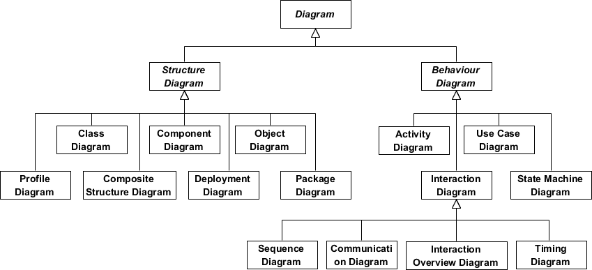
Structural Diagrams
- Class Diagram – diagram of the static structure of the system’s classes and interfaces and their relationships or associations (including inheritance, aggregation, and association) including the operations and attributes of the classes. Presentation modes are: Association, Inheritance, Dependency. This is a very common diagram in UML.
- Object Diagram – is a diagram of a static structure of a system at a specific time or situation (snap shot) illustrating a relationship in a system.
- Component Diagram – is a diagram that describes the organization and dependencies of components within the system.
- Composite Structure Diagram – is a diagram that explores run-time instances of interconnected instances collaborating over communications links.
- Package Diagram – is a diagram that depicts how a system is split up into logical groupings and what dependencies may exist among these groupings.
- Deployment Diagram – is a diagram the describes how distributable physical units (deployable software components, applications, servers, applications, hardware etc…) make up the distributed system architecture.
Behavior Diagrams
- Use Case Diagram – diagram of the use cases (software functions/services) and the role of the actors (users – both humans or systems). This diagram is from the user’s perspective.
- Activity Diagram – is a diagram of the dynamic nature of a system by modeling the flow of control from activity to activity. Diagram how a system (ie: object/class) responds to an internal event. (note: external events are described by an State Diagram). For business process modeling you can use this diagram to model the logic of a use case or business rule.
- State Diagram (aka State chart Diagram, State Machine Diagram) – is a diagram of how a system (ie: object/class) responds to an external event. (note: internal events are described by an Activity Diagram).
Interaction Type Diagrams – interactions of the organizational parts of the model.
- Sequence Diagram – is a diagram of the interaction and flow of messages among objects and the relative time ordering of the messages
- Communication Diagram (aka UML1’s Collaboration Diagrams ) – is a diagram of how systems collaborate together to perform a task and the associates that must exist between the systems. The collaboration diagram is a result of taking the Sequence diagram and describing it’s interaction with the Class Diagram. In summary, this diagram shows the message flow between objects and the basic associations (relationships) between classes
- Timing Diagram – is a diagram that explores the behaviors of one or more objects throughout a given period of time.
- Interaction Overview Diagram – is a diagram of the interaction and flow control between the interaction diagrams (sequence diagram, communication diagram, timing diagram, interaction overview diagram).
UML Profile
UML Profile is not exactly a diagram, but a profile to describe extensions and subsets to UML. Subsets are described using the Object Constraint Language (OCL). Extensions are created by defining stereotypes, which are tags that can decorate any model element. For example, we may tag a class “persistent” and use the tag to identify a class whose instances are stored past the lifetime of the run-time of the system. Informally—and this is ideologically unsound—a profile is any set of extensions and subset to UML whether written down using these mechanisms or not. Formally, a profile is the OCL and stereotype definitions that describe the rules, which in UML 2, are captured in a package.
Related Diagrams for Software Development
Between the differences of OOAD Methodologies & the evolution of UML standards the names of diagrams and their functions may evolve over time. Here are some examples of diagrams and/or work products that may or may not be apart of UML1 or UML2 but could be used in OOAD Methodologies:
- System Context Diagram
- Entity Relationship Diagram (similar to Class Diagram) with conceptual, logical and physical ERD
- Robustness Analysis
Conclusion
We have taken a look at the origins and definition of the UML to provide a simplistic understanding of what it is, and what the UML can offer us. We have also examined how we can benefit from its use on our next development project and briefly explored the architectural views and models and type of diagrams available in UML 2. UML is a not a process, but a open standard visual modeling notation for developing software intensive system. The components needed for a successful project require three facets: a notation, a process and a tool:
Notation Only – You can learn a notation (e.g UML), but if you don’t know how to use it (process), you will probably fail.
Process Only – You may have a great process, but if you can’t communicate the process (notation), you will probably fail. And lastly
No Tool Support – if you cannot effectively document the artifacts of your work (tool), you will probably end up waste a lot of time and eventually fail.
Automate UML Tool
Visual Paradigm is a automated tool that ensures you will be successful in your software projects with:
- Easy Syntax editing to minimize the need for notation memorization
- Support popular and most easy agile scrum software development process and toolset
- Automated to to streamline for any size of project and product report and artifact on-the fly
UML Resources
- Comprehensive Guide to the 14 UML Diagram Types – Cybermedian
- This guide provides an overview of the 14 UML diagram types supported by Visual Paradigm Community Edition. It explains how UML diagrams help in visualizing software-intensive systems and describes the functionality provided by each type of diagram. The guide also highlights the versatility of Visual Paradigm in supporting various UML diagrams for different modeling needs11.
- Learn UML modeling with the best UML free tools (both online and desktop freeware) – Cybermedian
- This article discusses the benefits of using Visual Paradigm for UML modeling, emphasizing its support for the latest UML 2.x standard and its extensive range of diagram types. It also mentions the tool’s integration capabilities with popular development platforms and its widespread adoption in academia and industry12.
- Learning by Example: UML State Machine Diagrams – Cybermedian
- This resource focuses on UML State Machine Diagrams and recommends Visual Paradigm as an ideal tool for creating these diagrams. It provides an in-depth look at how State Machine Diagrams can model dynamic system behavior and highlights Visual Paradigm’s integration with development tools and platforms13.
- UML Diagrams: A Comprehensive Guide – Cybermedian
- This comprehensive guide explains the importance of UML diagrams in software development and how Visual Paradigm supports various types of UML diagrams. It covers structural, behavioral, and interaction diagrams, providing insights into how Visual Paradigm can be used to create effective UML models14.
- FREE Online UML Tool – Cybermedian
- This article introduces Visual Paradigm Online (VP Online) Express Edition, a free online drawing tool for creating UML diagrams. It highlights the tool’s ease of use, lack of limitations, and compatibility with various web browsers, making it an accessible option for personal and non-commercial UML diagram creation15.
- Understanding UML Timing Diagrams: A Comprehensive Guide – Cybermedian
- This guide explains UML Timing Diagrams and their importance in real-time systems. It discusses how Visual Paradigm can be used to create these diagrams, focusing on the visual representation of timing and duration constraints within a system16.
- The Comprehensive Guide to UML 2.5 Diagrams – Cybermedian
- This guide provides an overview of UML 2.5 diagrams and highlights Visual Paradigm as a premier choice for comprehensive modeling. It discusses the tool’s versatility, user-friendly interface, and robust code generation capabilities, making it suitable for professionals across various industries17.
- A Comprehensive Guide to UML Class Diagram – Cybermedian
- This guide focuses on UML Class Diagrams and how Visual Paradigm supports their creation. It discusses the tool’s widespread adoption in academia and its use in system and database design and analysis. The guide also mentions the availability of examples and templates for quick start with UML modeling18.
- UML Package Diagram Tutorial Using Visual Paradigm – Cybermedian
- This tutorial walks through the steps to create a UML Package Diagram using Visual Paradigm. It explains the importance of package diagrams in organizing large systems and provides a step-by-step guide on creating them using Visual Paradigm19.
- The Comprehensive Guide to Visual Modeling for Agile Software Development – Cybermedian
- This guide discusses the role of UML tools in agile software development and highlights Visual Paradigm as a popular choice. It explains how Visual Paradigm provides a user-friendly interface and features such as validation, code generation, and reverse engineering to enhance the modeling process20.
