


A comprehensive reference for software engineers, architects, and development teams

What is UML?
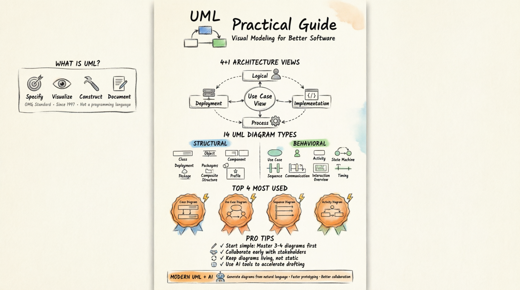
Unified Modeling Language (UML) is a standard, general-purpose visual modeling language for specifying, visualizing, constructing, and documenting the artifacts of software systems. Created by the Object Management Group (OMG), the UML 1.0 specification draft was first proposed in January 1997.
Key Characteristics
✅ General-purpose: Models both software and non-software systems (e.g., manufacturing workflows)
✅ Visual: Uses standardized diagrams to communicate complex ideas
✅ Language-agnostic: Not a programming language, but tools can generate code from UML diagrams
✅ Object-oriented: Follows OO concepts—objects, classes, inheritance, polymorphism
✅ Standardized: OMG-maintained specification ensures consistency across tools and teams
Core Principles for Developers
🔹 Objects are central: Identify objects → Assign responsibilities → Design interactions
🔹 UML supports the full lifecycle: Requirements → Analysis → Design → Implementation → Deployment
🔹 Diagrams serve different audiences: Developers, testers, business stakeholders, architects
🔹 UML complements methodologies: Works with Agile, Waterfall, DevOps—not a replacement
Purpose & Benefits
“A picture is worth a thousand words” — especially true for system design.
Why UML Matters for IT Developers
| Benefit | Developer Impact |
|---|---|
| Standardized notation | Reduces ambiguity; improves team communication |
| Visual abstraction | Simplifies complex systems into understandable components |
| Early validation | Catch design flaws before coding begins |
| Documentation | Self-documenting diagrams reduce knowledge silos |
| Tool integration | Generate code, reverse-engineer, validate architecture |
| Stakeholder alignment | Bridge technical and non-technical audiences |
What UML Is NOT
❌ Not a development methodology
❌ Not a programming language
❌ Not mandatory for every project
❌ Not a substitute for working code
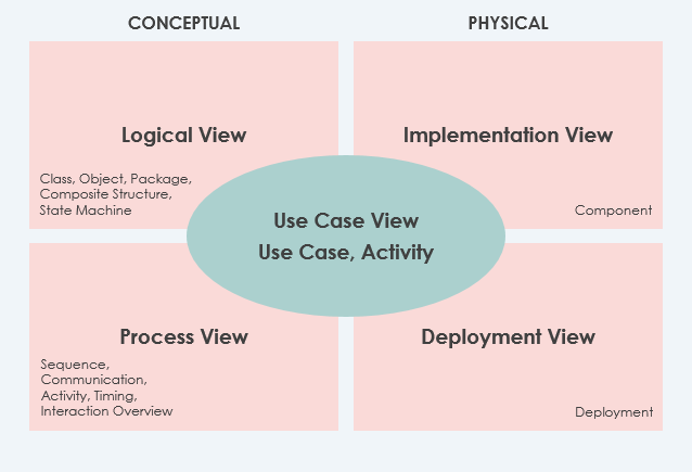
Modeling Architecture: The 4+1 Views
Different stakeholders view systems differently. The 4+1 View Model helps architects capture multiple perspectives, with UML diagrams mapping to each view.
The Five Views Explained
🔹 Use Case View (The “+1” — Central & Mandatory)
-
Purpose: Captures functional requirements and user interactions
-
Key UML Diagram: Use Case Diagram
-
Audience: Business analysts, product owners, testers
-
Tip: Start here—derive all other views from use cases
🔹 Logical View (Mandatory)
-
Purpose: Shows system structure in terms of classes, interfaces, packages
-
Key UML Diagrams: Class Diagram, Object Diagram, Package Diagram
-
Audience: Developers, architects
-
Tip: Focus on abstractions, not implementation details
🔹 Implementation View (Optional)
-
Purpose: Organizes development artifacts (files, directories, modules)
-
Key UML Diagrams: Component Diagram, Package Diagram
-
Audience: Build engineers, DevOps
-
Tip: Map to your repository structure and build system
🔹 Process View (Optional)
-
Purpose: Models runtime behavior: processes, threads, concurrency
-
Key UML Diagrams: Sequence Diagram, Activity Diagram, State Machine
-
Audience: Performance engineers, system architects
-
Tip: Critical for distributed systems and microservices
🔹 Deployment View (Optional)
-
Purpose: Maps software components to hardware infrastructure
-
Key UML Diagram: Deployment Diagram
-
Audience: Infrastructure teams, SREs
-
Tip: Include network topology, containers, cloud services
🔹 Data View (Specialized Logical View)
-
Purpose: Models persistence layer when auto-mapping isn’t sufficient
-
Key UML Diagrams: Class Diagram (with stereotypes), ER-style extensions
-
Audience: Database architects, backend developers
The 14 UML Diagram Types
UML 2.x defines 14 diagram types, categorized as Structural (static) or Behavioral (dynamic).
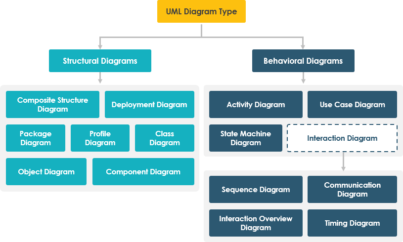
🔷 Structural Diagrams (Static Structure)
Show the static architecture—what the system is made of.
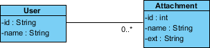
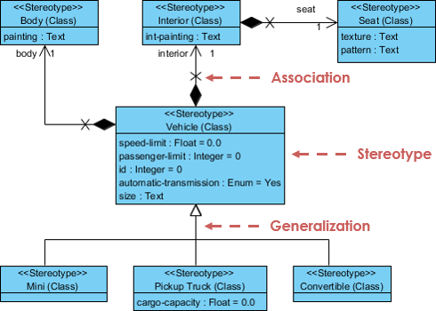
1. Class Diagram
Purpose: Models classes, attributes, operations, and relationships. The backbone of OO design.
When to use:
-
Designing domain models
-
Defining APIs and interfaces
-
Code generation & reverse engineering
Key elements: Classes, interfaces, associations, inheritance, multiplicity
💡 Developer Tip: Use stereotypes like
<<entity>>,<<service>>,<<repository>>to clarify roles. Keep diagrams focused—split large systems into packages.
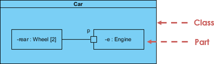
2. Object Diagram
Purpose: Shows instances of classes at a specific moment—a “snapshot” of runtime state.
When to use:
-
Debugging complex object interactions
-
Illustrating test scenarios
-
Validating class diagram logic
Key elements: Objects (instances), links, attribute values
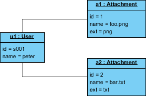
💡 Developer Tip: Use object diagrams sparingly—they’re great for examples but don’t scale for full system documentation.
3. Component Diagram
Purpose: Models physical software components (libraries, modules, executables) and their dependencies.
When to use:
-
Microservices architecture
-
Plugin systems
-
Build & deployment planning
Key elements: Components, interfaces, ports, dependencies
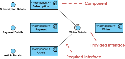
💡 Developer Tip: Align components with your module/package structure. Use provided/required interfaces to define contracts.
4. Deployment Diagram
Purpose: Maps software artifacts to hardware nodes (servers, containers, devices).
When to use:
-
Cloud infrastructure design
-
On-premise deployment planning
-
IoT system architecture
Key elements: Nodes, artifacts, communication paths, execution environments
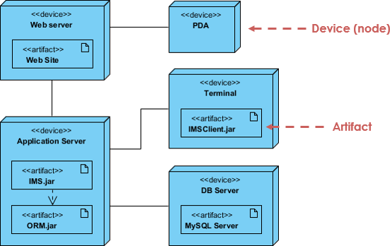
💡 Developer Tip: Include containerization details (Docker, Kubernetes) and cloud services (AWS, Azure) as stereotypes.
5. Package Diagram
Purpose: Organizes model elements into namespaces/packages to manage complexity.
When to use:
-
Large-scale system modularization
-
Layered architecture documentation
-
Dependency management
Key elements: Packages, dependencies, imports, merges
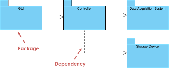
💡 Developer Tip: Follow the “stable dependencies principle”—packages should depend on more stable abstractions.
6. Composite Structure Diagram
Purpose: Shows internal structure of a class/component and how parts collaborate at runtime.
When to use:
-
Complex component design
-
Pattern implementation (e.g., Strategy, Composite)
-
Runtime collaboration modeling
Key elements: Parts, ports, connectors, collaborations
💡 Developer Tip: Use this for documenting internal workflows of microservices or complex domain objects.
7. Profile Diagram
Purpose: Defines domain-specific extensions (stereotypes, tagged values, constraints) to UML.
When to use:
-
Creating custom DSLs
-
Enforcing architectural rules
-
Tool-specific modeling extensions
Key elements: Stereotypes, metaclasses, tagged values, constraints
💡 Developer Tip: Use profiles to enforce team conventions (e.g.,
<<spring-controller>>,<<kafka-producer>>).
🔶 Behavioral Diagrams (Dynamic Behavior)
Show how the system behaves over time—interactions, state changes, workflows.
8. Use Case Diagram
Purpose: Captures functional requirements via actors and use cases.
When to use:
-
Requirements gathering
-
Sprint planning
-
Stakeholder communication
Key elements: Actors, use cases, associations, include/extend relationships
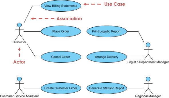
💡 Developer Tip: Keep use cases at user-goal level. Avoid system-level functions—focus on user value.
9. State Machine Diagram
Purpose: Models the lifecycle of an object through states, transitions, and events.
When to use:
-
Workflow engines
-
Order processing systems
-
UI state management
Key elements: States, transitions, events, guards, actions
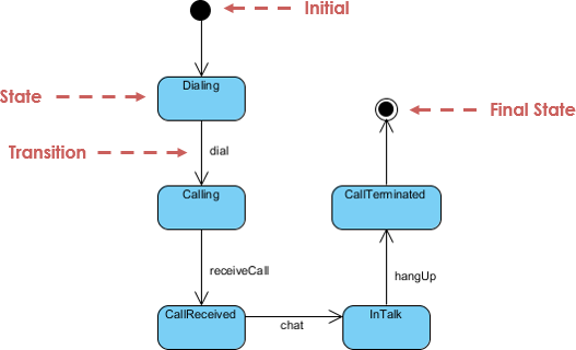
💡 Developer Tip: Use hierarchical states to manage complexity. Validate state transitions with unit tests.
10. Activity Diagram
Purpose: Models workflows, business processes, or algorithmic logic as a flow of activities.
When to use:
-
Business process modeling
-
Algorithm design
-
Parallel/concurrent flow visualization
Key elements: Activities, decisions, forks/joins, swimlanes, object flows
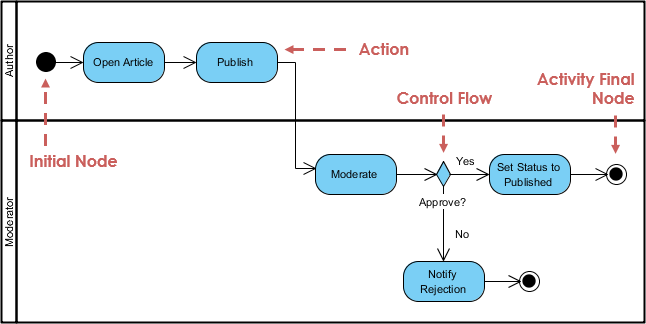
💡 Developer Tip: Use swimlanes to assign responsibilities to roles/services. Great for documenting async workflows.
11. Sequence Diagram
Purpose: Shows object interactions arranged in time sequence—who calls whom, when, and with what.
When to use:
-
API design & documentation
-
Debugging distributed systems
-
Explaining complex workflows
Key elements: Lifelines, messages, activation bars, fragments (alt/opt/loop)
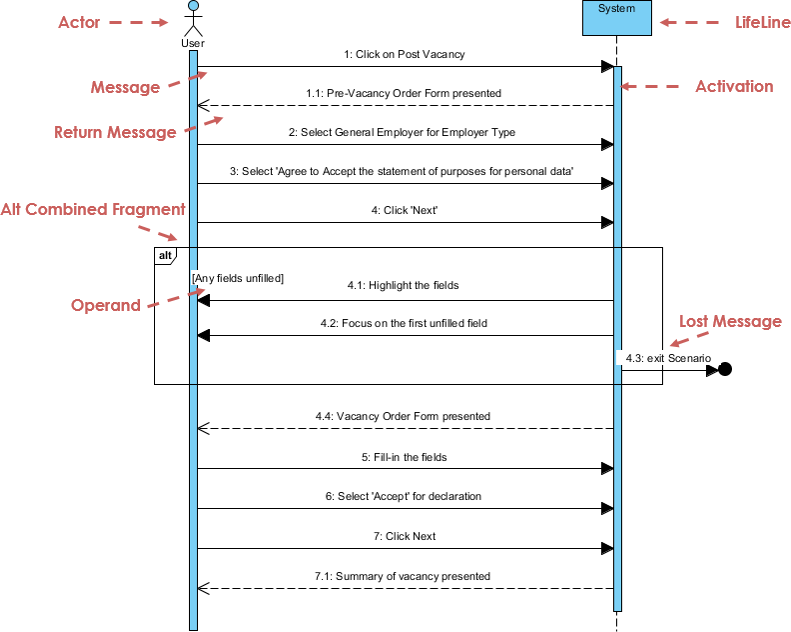
💡 Developer Tip: Keep sequences focused on one scenario. Use “ref” fragments to link to other diagrams for modularity.
12. Communication Diagram (formerly Collaboration Diagram)
Purpose: Emphasizes object relationships and message flow over time sequencing.
When to use:
-
When object topology matters more than timing
-
Refactoring object collaborations
-
Complementing sequence diagrams
Key elements: Objects, links, numbered messages
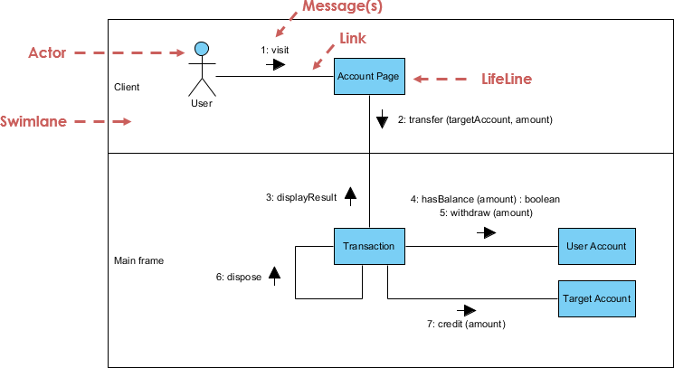
💡 Developer Tip: Use communication diagrams to visualize dependency graphs. Tools can auto-convert between sequence/communication views.
13. Interaction Overview Diagram
Purpose: High-level flow of control between interactions—combines activity and sequence diagrams.
When to use:
-
Orchestrating complex multi-step processes
-
Documenting system-wide workflows
-
Linking detailed interaction diagrams
Key elements: Interaction occurrences, control flow, decision nodes
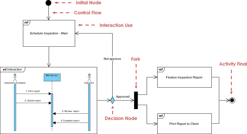
💡 Developer Tip: Use this as a “table of contents” for detailed sequence diagrams—improves navigability in large models.
14. Timing Diagram
Purpose: Focuses on time constraints and state changes over precise time intervals.
When to use:
-
Real-time systems
-
Hardware/software co-design
-
Performance-critical protocols
Key elements: Lifelines, state timelines, time constraints, duration constraints
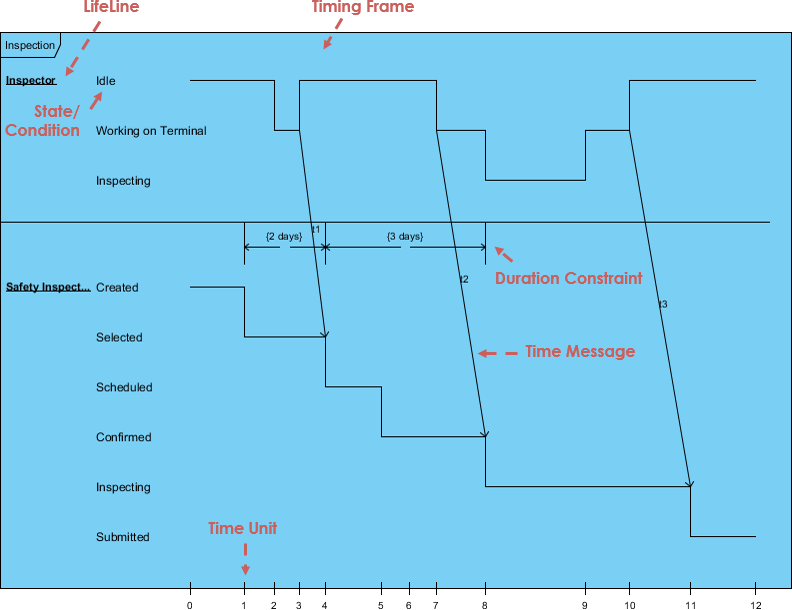
💡 Developer Tip: Rarely needed for business applications. Reserve for embedded systems, IoT, or high-frequency trading platforms.
Practical Tips & Tricks for Developers
🎯 Diagram Selection Cheat Sheet
| Goal | Recommended Diagram(s) |
|---|---|
| Design domain model | Class Diagram + Object Diagram |
| Document API contracts | Class Diagram + Sequence Diagram |
| Plan microservices | Component Diagram + Deployment Diagram |
| Model user workflows | Use Case Diagram + Activity Diagram |
| Debug race conditions | Sequence Diagram + Timing Diagram |
| Visualize state logic | State Machine Diagram |
| Organize large codebase | Package Diagram + Component Diagram |
| Explain to stakeholders | Use Case Diagram + simplified Class Diagram |
🛠️ Tooling & Workflow Tips
graph LR
    A[Requirements] --> B[Use Case Diagram]
    B --> C[Class/Component Diagrams]
    C --> D[Sequence/Activity Diagrams]
    D --> E[Code Generation]
    E --> F[Reverse Engineer for Docs]
    F --> G[Iterate & Refine]
✅ Start simple: Sketch on whiteboard → digitize in tool
✅ Version control diagrams: Store .uml or .vp files in Git
✅ Keep diagrams alive: Update alongside code—outdated diagrams hurt more than help
✅ Use stereotypes consistently: <<controller>>, <<entity>>, <<api>> improve readability
✅ Leverage tool automation: Generate sequence diagrams from code; reverse-engineer class diagrams
✅ Document decisions: Add notes to diagrams explaining why a design choice was made
🚫 Common Pitfalls to Avoid
| Pitfall | Solution |
|---|---|
| Over-engineering diagrams | Focus on communication, not completeness |
| Ignoring audience | Tailor detail level: architects need depth, PMs need clarity |
| Static documentation | Treat diagrams as living artifacts—review in sprint retros |
| Mixing abstraction levels | Keep one concern per diagram; use packages to organize |
| Forgetting non-functional needs | Add notes for performance, security, scalability constraints |
Best Practices for UML Adoption
For Agile Teams
-
Just-in-time modeling: Create diagrams during sprint planning, not upfront
-
Collaborative modeling: Use whiteboarding sessions with dev + QA + PO
-
Minimal viable diagrams: Only model what adds value—avoid “diagram bloat”
-
Embed in CI/CD: Auto-generate API docs from class diagrams; validate architecture rules
For Enterprise Architects
-
Establish modeling standards: Define stereotype libraries, naming conventions, toolchain
-
Create reference architectures: Template diagrams for common patterns (microservices, event-driven)
-
Govern with profiles: Enforce architectural rules via UML profiles and validation scripts
-
Bridge views: Ensure traceability from Use Case → Logical → Deployment views
For Individual Developers
-
Learn the 20% that delivers 80%: Master Class, Sequence, Use Case, Activity diagrams first
-
Use diagrams for onboarding: Help new team members understand system structure
-
Document complex logic: A well-crafted state diagram beats 100 lines of comments
-
Pair diagramming: Review diagrams in code reviews—treat as design documentation
AI-Powered UML Tools
Modern tooling accelerates UML adoption. Visual Paradigm’s AI ecosystem bridges natural language and professional diagrams:
💬 AI Diagram Chatbot
Instant diagram drafting through natural conversation. Perfect for quickly capturing use case views and system behaviors.
🌐 AI WebApps
Step-by-step AI-guided workflows to create and evolve your architecture from simple sketches to detailed implementation views.
⚡ AI Diagram Generator
Generate professional UML diagrams directly within the Visual Paradigm Desktop, ensuring full compliance with OMG standards.
📝 OpenDocs
A modern knowledge management system to centralize your documents and embed live AI-generated diagrams.
🚀 Ready to modernize your modeling process?
Explore the AI Diagramming Ecosystem →
Reference List
What is UML? A Comprehensive Guide to Unified Modeling Language: This in-depth introduction explains the fundamental concepts of UML and its critical role in software design and system modeling.
Overview of the 14 UML Diagram Types – Visual Paradigm: This resource explores the 14 distinct UML diagram types, each serving specific modeling purposes with standardized notation.
Practical Guide to UML: From Theory to Real-World Application: A hands-on tutorial that demonstrates how to apply use case, class, sequence, and activity diagrams to real software projects.
Adopting UML in Agile Projects: A Complete Tutorial with Visual Paradigm: This article provides guidance on integrating UML modeling into Agile workflows to improve planning, communication, and project clarity.
AI-Powered UML Class Diagram Generator by Visual Paradigm: This tool utilizes a Generative AI engine to transform natural language descriptions into accurate UML class diagrams automatically.
Visual Paradigm – AI-Powered UML Sequence Diagrams: This resource teaches users how to generate professional UML sequence diagrams instantly from simple text prompts using advanced AI modeling.
What Is a Use Case Diagram? – A Complete Guide to UML Modeling: An in-depth explanation of use case components and best practices for requirements modeling and system design.
What is a Package Diagram in UML? – Visual Paradigm Guide: This guide focuses on organizing and managing complex systems through the logical grouping of elements using package diagrams.
What is a Deployment Diagram? A Complete Guide to UML Deployment Diagrams: This comprehensive guide explains how to model the physical architecture of a software system, including hardware and software mapping.
UML Diagrams Explained: A Beginner’s Guide: A clear, foundational resource that introduces the key types of UML diagrams and their practical applications in the software development lifecycle.
