


A User Experience Guide to Modeling Dynamic System Behavior
🌟 Introduction: Why Your Systems Need a State of Mind
🔹 Communicate behavior across design, development, and QA teams
🔹 Anticipate edge cases by explicitly modeling every possible state
🔹 Document system intent in a way that stays accurate as requirements evolve
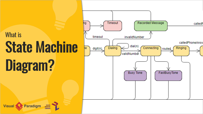
🚀 Starting Your Journey: What Is a State Machine Diagram?
Welcome, traveler! Imagine you’re designing a smart thermostat, an e-commerce checkout flow, or a banking system. How do you capture how an object behaves over time—especially when its response to the same event changes based on what happened before?
That’s where State Machine Diagrams come in.
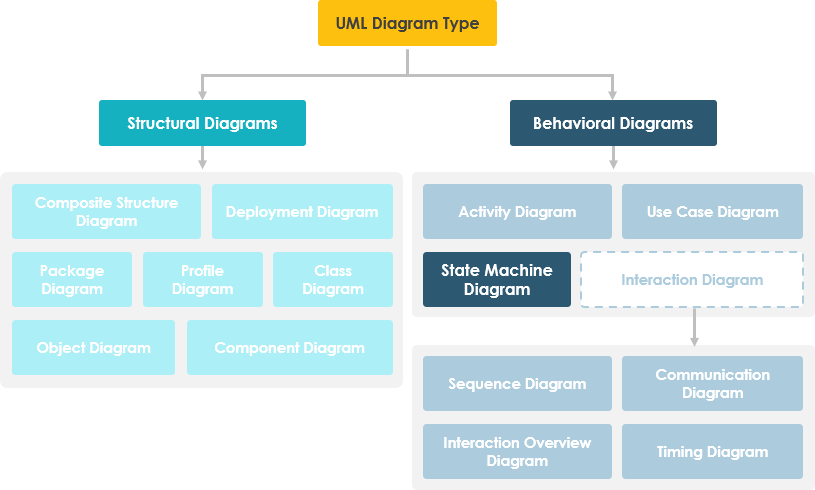
A State Machine Diagram (also called a state diagram, state machine, or state chart) is a UML behavioral diagram that models the dynamic nature of a system by showing the different states an entity can be in, and how it transitions between those states in response to events.
The behavior of an entity isn’t just about its current input—it depends on its preceding state. The past history of an entity is best modeled by a finite state machine diagram (traditionally called automata).
🔹 Key Insight: State machine diagrams help you visualize lifecycle behavior—perfect for objects whose behavior changes based on context.
❓ Why Should You Care? The Value of State Machine Diagrams

As you progress on your journey, you’ll discover that an object responds differently to the same event depending on what state it is in.
💡 Real-World Example: Bank Account Withdrawal
Consider a bank account with $100,000:
-
✅ Normal withdrawal:
balance := balance - withdrawAmount(if balance ≥ $0) -
❌ Overdraft scenario: If withdrawal would make balance negative, different rules apply
This isn’t just about math—it’s about state-dependent behavior. When the account transitions from “Positive” to “Negative” state, the system’s behavior changes fundamentally.
⚠️ Note:
A state machine diagram describes all events, states, and transitions for a single object.
A sequence diagram describes events for a single interaction across all objects.
State machine diagrams are typically applied to objects but can model behavior for actors, use cases, methods, subsystems, and more—often used alongside interaction diagrams.
🧭 Your First Steps: Basic Concepts of State Machine Diagrams

🎯 What Is a State?
“A state is an abstraction of the attribute values and links of an object. Sets of values are grouped together into a state according to properties that affect the gross behavior of the object.”
— Rumbaugh
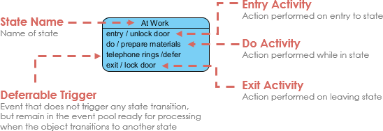
State Notation
🔑 Core Characteristics of States
-
✅ A state occupies an interval of time
-
✅ Represents an abstraction of attribute values satisfying certain conditions
-
✅ Behavior depends not just on current input, but on past history
🔄 State Machine Diagram Structure
A state machine diagram is a graph consisting of:
-
States (simple or composite)
-
State transitions connecting the states
What States Represent:
-
Conditions of objects at specific points in time
-
Points in a lifecycle where actions are performed or events are awaited
-
Opportunities for objects/systems to move from one condition to another
🧰 Building Your Toolkit: Characteristics of State Machine Notations

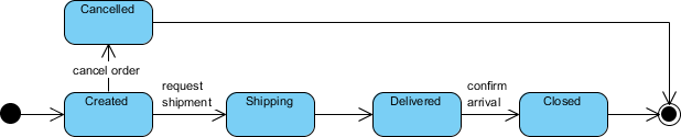
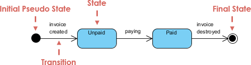
🟢 Initial and Final States
| Element | Symbol | Purpose |
|---|---|---|
| Initial State | ● Solid circle | Marks where the state machine begins; first transition leads to the first real state |
| Final State | ◎ Concentric circles | Marks termination; open-loop = object may end early; closed-loop = lives until system ends |
⚡ Events: The Triggers of Change
An event signature: Event-name(param1, param2, ...)
Four Types of Events:
-
Signal Event – Arrival of an asynchronous message/signal
-
Call Event – Procedural call to an operation
-
Time Event – Occurs after specified time elapses
-
Change Event – Triggered when a condition becomes true
Event Characteristics:
-
🎯 Represent incidents causing state transitions
-
🔁 Can be internal or external
-
💬 Pass information elaborated by object operations
-
🛠️ Design involves mapping events to system object support
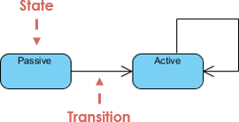
➡️ Transitions: The Pathways Between States
Transitions depict movement from one state to another, labeled with the event that triggers them.
Transition Flow:
-
Element is in source state
-
Event occurs
-
Action is performed
-
Element enters target state
✨ Pro Tip: A transition without an event/action is an automatic transition.
⚙️ Actions vs. Activities
| Concept | Definition | Key Trait |
|---|---|---|
| Action | Atomic, uninterruptible computation (e.g., operation call, object creation) | Completes without interruption |
| Activity | Non-atomic, ongoing computation associated with a state | May run indefinitely or be interrupted by events |
Action Triggers (5 Types):
-
entry / action– Executes when entering a state -
do / activity– Ongoing behavior while in state -
event / action– Executes on specific event while in state -
exit / action– Executes when leaving a state -
include / behavior– Reuses defined behavior
💡 Key Difference: Actions are atomic; activities can be interrupted.
🎨 Putting It Into Practice: Simple State Machine Diagram Notation
🚪 Entry and Exit Actions
These ensure consistent behavior whenever a state is entered or exited.
-
Entry Action:
entry / action– Executes on every entry via transition -
Exit Action:
exit / action– Executes on every exit via transition
⚠️ If behavior isn’t consistent for all entries/exits, use actions on individual transition arcs instead.
Example: BookCopy Status Lifecycle
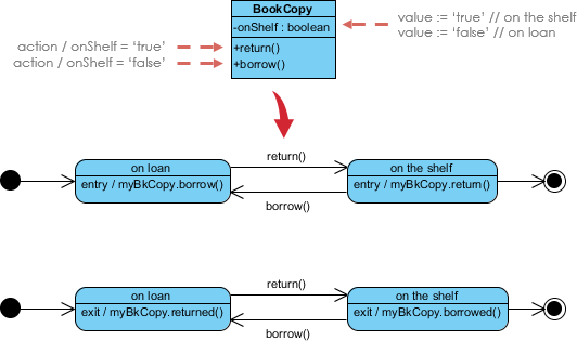
🔹 Notes:
-
Models state of
myBkCopyobject fromBookCopyclass -
Entry actions fire whenever the state is entered
-
Exit actions fire whenever the state is left
🧠 Advanced Techniques: Mastering Complex Lifecycles
📦 Substates: Nesting for Clarity
A simple state has no substructure. A composite state contains nested substates.
✨ Substates simplify complex flat state machines by showing that some states are only possible within a particular context (the enclosing state).
Example: Heater Control System
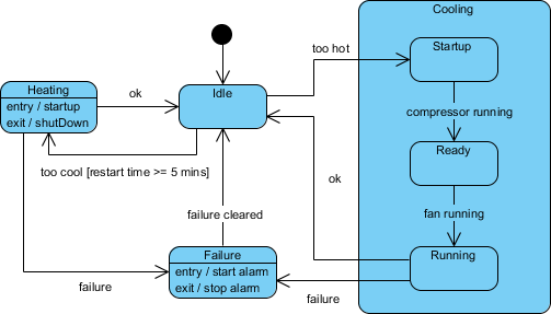
🔹 Testing Ideas Derived from This Diagram:
-
Idle state receives “Too Hot” event
-
Idle state receives “Too Cool” event
-
Cooling/Startup receives “Compressor Running”
-
Cooling/Ready receives “Fan Running”
-
Cooling/Running receives “OK” or “Failure”
-
Failure state receives “Failure Cleared”
-
Heating state receives “OK” or “Failure”
🕰️ History States: Remembering Where You Were
By default, entering a composite state restarts its nested machine from the initial state. History states let you re-enter the last active substate.
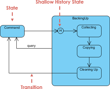
💡 Use case: Pausing/resuming a multi-step workflow without losing progress.
⚡ Concurrent States: Modeling Parallel Behavior
When an activity involves concurrent sub-activities, group related states into a composite state with parallel regions.
Example: Auction Process
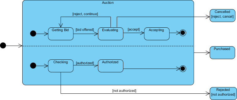
🔹 How It Works:
-
Entering “Auction” forks into two parallel threads: Process Bid and Authorize Payment
-
Each substate has its own exit condition
-
Composite state exits only when both substates complete (unless abnormal exit: Canceled/Rejected)
🤖 Supercharge Your Journey: AI-Powered State Machine Design
State machines are essential for modeling event-driven behavior—but nested substates and concurrent regions can be challenging to design manually.
✨ Visual Paradigm’s AI Tools Simplify This:
🖥️ VP Desktop
-
Integrated AI assistant generates and refines state-dependent logic directly within the UML modeler
💬 AI Chatbot
-
Describe your object’s states and transitions to AI Chat for instant, editable diagram generation
🚀 Smart Behavioral Design Features:
🔄 Transition Discovery: AI automatically identifies states and transitions from your requirements
🛡️ Time Saving: Generate diagrams in one click, in seconds
Learn More about AI State Diagramming | Full AI Ecosystem
🧭 Your Journey Checklist: Key Takeaways
✅ State Machine Diagrams model dynamic, state-dependent behavior
✅ States represent abstractions of attribute values affecting object behavior
✅ Transitions are triggered by events and may include actions
✅ Entry/exit actions ensure consistent behavior at state boundaries
✅ Substates, history states, and concurrent regions handle complexity
✅ AI tools can accelerate design and reduce manual errors
📚 Reference List
- Mastering State Diagrams with Visual Paradigm AI: A Guide for Automated Toll Systems: This guide demonstrates how to use AI-enhanced state diagrams to model and automate complex behavior within toll system software.
- AI-Powered UML Chatbot State Diagrams: This article explores how artificial intelligence enhances the creation and interpretation of UML state diagrams specifically for chatbot systems.
- UML State Machine Diagram: A Definitive Guide to Modeling Object Behavior with AI: This resource provides a detailed guide on using AI-enhanced tools to model object behavior with standardized state machine notation.
- Comprehensive Step-by-Step Guide to the 3D Printer State Machine: A detailed walkthrough that explains the state machine concept in 3D printing systems and the operational logic used to automate them.
- State Diagram Quick Tutorial: Master UML State Machines in Minutes: A beginner-friendly tutorial designed to help users master the creation and understanding of state diagrams using modern modeling tools.
- Generating Source Code from State Machines in Visual Paradigm: This technical guide provides instructions on generating source code directly from diagrams, enabling developers to implement complex state-driven logic efficiently.
- What is a State Machine Diagram? A Comprehensive Guide to UML State Diagrams: This guide provides an in-depth explanation of state machine purposes, components, and real-world applications in modern system design.
- AI-Powered Visual Modeling and Design Solutions by Visual Paradigm: This central hub explores cutting-edge AI-driven tools for visual modeling and software design, enabling smarter development workflows for UML diagrams including state machines.
- How AI Chatbot Can Help You Learn UML Faster: This article explains how users can practice UML interactively, receive feedback, and visualize concepts instantly using an AI modeling partner.
- AI Textual Analysis – Transform Text into Visual Models Automatically: This feature overview details how to use AI to analyze text documents and automatically generate diagrams, such as UML state machines, for faster documentation.
💬 Final Thought: State Machine Diagrams aren’t just documentation—they’re living blueprints for robust, predictable system behavior. As you continue your UX and systems design journey, let state machines be your compass for navigating complexity with clarity. 🧭✨
